Outer frame of backlight module unit

A backlight module and frame technology, applied in optics, nonlinear optics, instruments, etc., can solve the problems of increased manufacturing costs, operator fatigue, collision and scratches, etc., to reduce the difficulty of disassembly and assembly, and improve the disassembly and assembly. Speed, the effect of reducing operation time

Inactive Publication Date: 2009-04-22
CORETRONIC (SUZHOU) CO LTD
View PDF0 Cites 6 Cited by
  • Summary
  • Abstract
  • Description
  • Claims
  • Application Information

AI Technical Summary

Problems solved by technology

[0004] For the hook-type assembly structure mentioned above, in order to ensure the compactness of the whole structure and fit in place, the fit size of the hook and the square hole is often designed to be relatively compact, which will make it very difficult for the operator to disassemble, and the entire backlight module needs to be lifted. High, which increases the complexity of the operation and is easy to cause fatigue to the operator. If the operation is careless, it will cause the optical film (Optic Films) of the display to shift up and down or collide with scratches and other adverse consequences, thereby reducing the yield of the production line and increasing the manufacturing capacity. cost

Method used


Image

  • Outer frame of backlight module unit
  • Outer frame of backlight module unit
  • Outer frame of backlight module unit

Examples


Embodiment Construction

[0015] The directional terms mentioned in the following embodiments, such as: up, down, left, right, front or back, etc., are only directions referring to the attached drawings. Accordingly, the directional terms are used to illustrate and not to limit the invention.

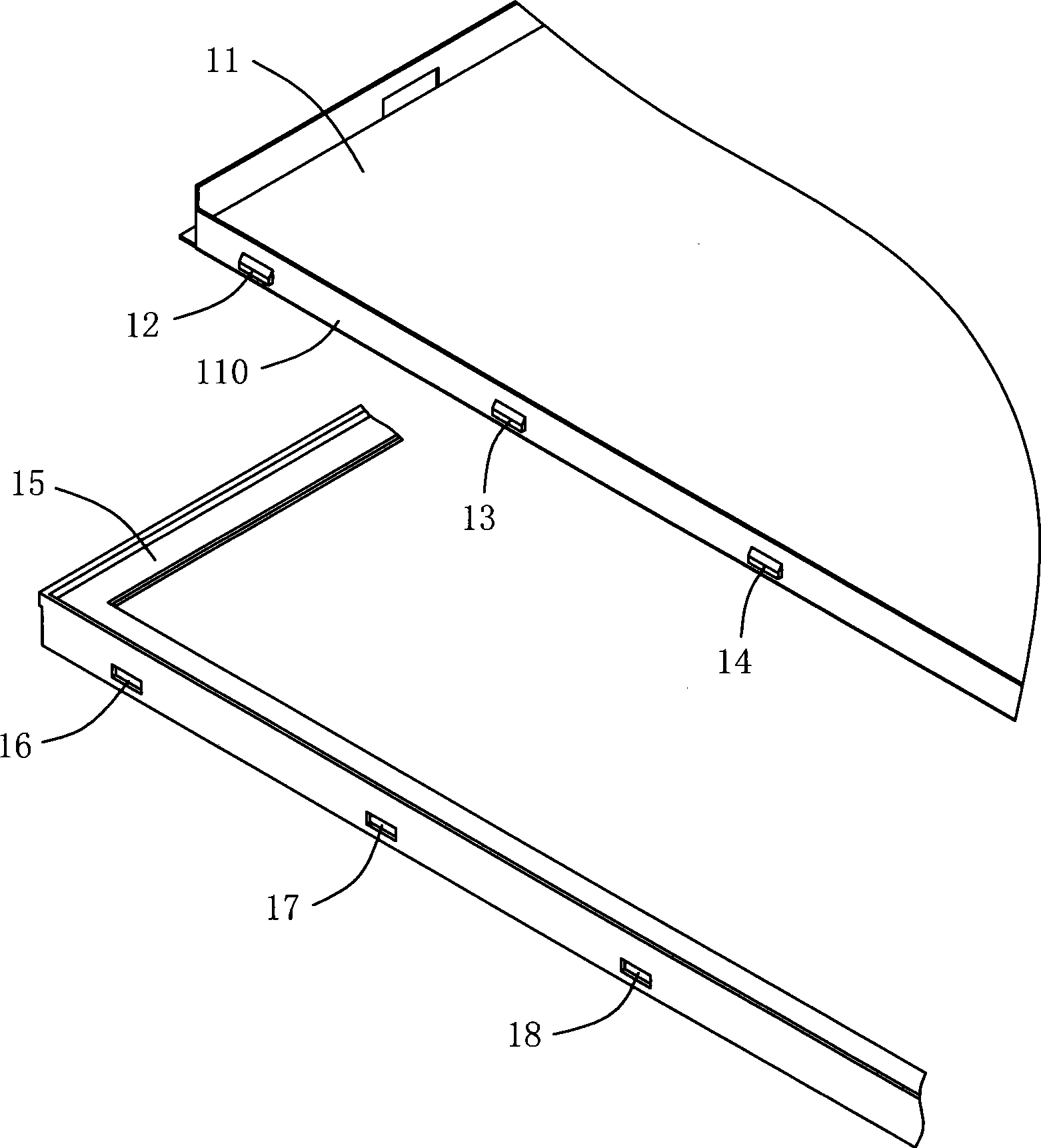
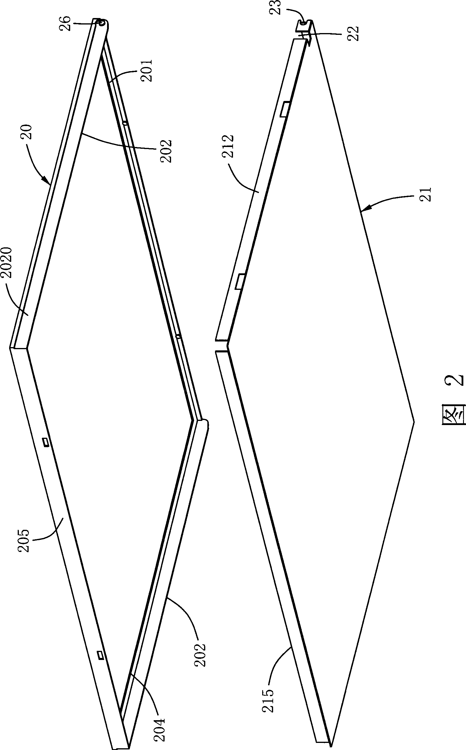
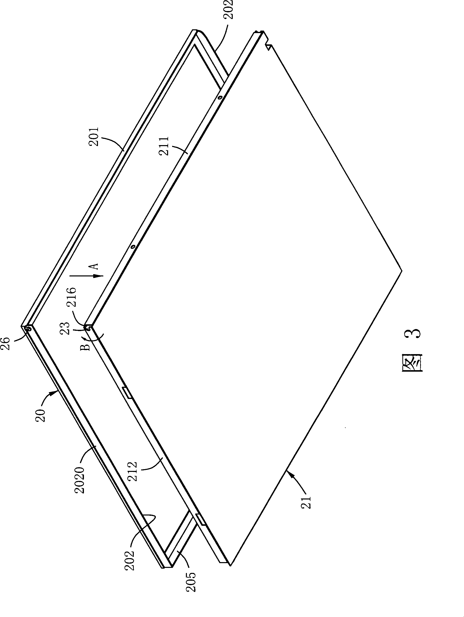
[0016] Please refer to FIG. 2 and FIG. 3, according to a preferred embodiment of the present invention, it provides an outer frame of a detachable backlight module, the outer frame includes an upper frame 20 and a back plate 21, with corresponding The shapes and sizes can be combined with each other to form the frame of the backlight module.

[0017] The upper frame 20 can be made of appropriate material and has an appropriate shape. In this embodiment, the upper frame 20 is made of plastic material. In this embodiment, the upper frame 20 is rectangular and has a first upper frame side 201, two second upper frame sides 202 and two pivot portions 26, wherein the two second upper frame sides 202 are parallel to ...


PUM


Abstract

The invention discloses an outer frame of a backlight model, comprising an upper frame and a backing plate; wherein, the upper frame is provided with a first upper frame side, two second upper frame sides and two pivotal parts, and the two second upper frame sides are mutually parallel and vertical to the first upper frame side; the two pivotal parts are respectively arranged at the two second upper frame sides. The backing plate is provided with a first backing plate side, two second backing plate sides and two coupling parts, wherein, the two second backing plate sides are mutually parallel and vertical to the first backing plate side, and the two coupling parts are respectively arranged at the two backing plate sides. The two pivotal parts of the upper frame and the two coupling parts of the backing plate are corresponding to each other and connected with each other to form two pivot structures.

Description

【Technical field】 [0001] The present invention relates to an outer frame of a backlight module, in particular to an outer frame structure of a detachable backlight module. 【Background technique】 [0002] Backlight modules are usually used in liquid crystal displays to provide light sources for them. The outer frame of the backlight module is usually interlocked with the upper frame and the back plate to fix the components installed inside the outer frame. During the assembly process, it is unavoidable to need to rework and rework to open the frame. Therefore, whether the design of the assembly structure of the backlight module frame is easy to assemble and disassemble will seriously affect the finished product yield and production speed. [0003] The assembly structure of the frame of the traditional backlight module is mostly designed as a hook-type positioning, wherein a considerable number of hooks are used. figure 1 2 shows a three-dimensional schematic diagram of the ...

Claims


Application Information

Patent Timeline
Patent Type & Authority Applications(China)
IPC IPC(8): G02F1/1333
Inventor 朱欣欣黄春平
Owner CORETRONIC (SUZHOU) CO LTD
Why Eureka
Try Eureka