An instantaneous power factor compensation control method and system
A compensation control and instantaneous power technology, applied in reactive power compensation, reactive power adjustment/elimination/compensation, harmonic reduction device, etc., can solve problems such as slow response speed
- Summary
- Abstract
- Description
- Claims
- Application Information
AI Technical Summary
Problems solved by technology
Method used
Image
Examples
Embodiment 1
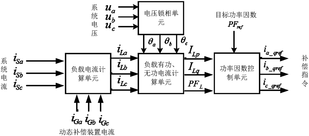
[0055] The instantaneous power factor compensation control system in this embodiment is as follows figure 2 As shown, it includes a load current calculation unit, a load active and reactive current calculation unit, a voltage phase-locked unit and a power factor control unit. The system calculates the load instantaneous active current component and reactive current component in real time through the load active and reactive current calculation unit to obtain the load instantaneous power factor, and calculates the instantaneous power factor control value through the power factor control unit. The specific working process of this unit is as follows:
[0056] The load current calculation unit is used to calculate the three-phase load current i according to the three-phase system current and the three-phase current output by the dynamic compensation device La i Lb i Lc , the calculation formula of the three-phase load current used is:
[0057]
[0058] where i La is the i...
Embodiment 2
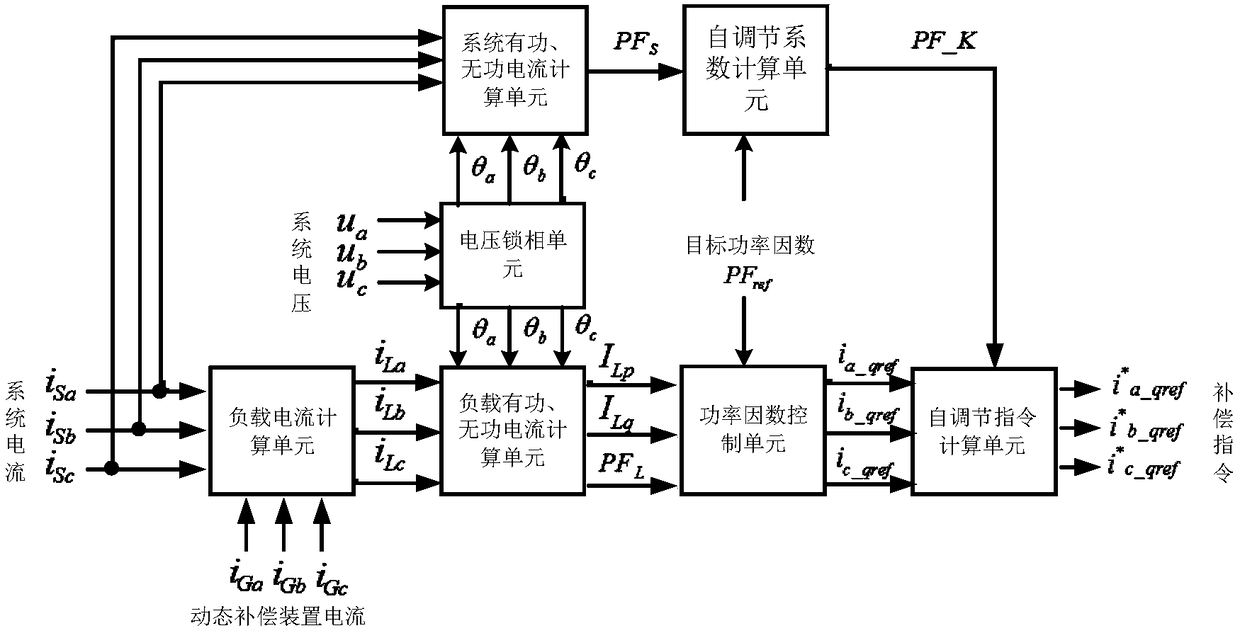
[0090] In order to make up for the control error problem caused by device parameter changes, the present invention, on the basis of Embodiment 1, calculates the instantaneous value i of the three-phase reactive power compensation control quantity obtained by the power factor control unit a_qref i b_qref i c_qref self-regulating, such as image 3 As shown, on the basis of the first embodiment, the system also includes a system power and reactive current calculation unit, a self-regulation coefficient calculation unit and a self-regulation command calculation unit. The system works as follows:
[0091] The system active and reactive current calculation unit decomposes the three-phase system current into the active current component I Sp , reactive current component I Sq And the instantaneous power factor PF of the system after compensation S , the formula used is:
[0092]
[0093]
[0094] The self-adjusting coefficient calculation unit is used to calculate the inst...
Embodiment 3
[0103] In order to make the instantaneous power factor compensation control system of the present invention applicable to the occasion of voltage and current distortion, the instantaneous power factor compensation control system in this embodiment is further improved on the basis of the second embodiment, as Figure 4 As shown, the system active and reactive current calculation unit, the voltage phase-locked unit and the load active and reactive current calculation unit are all equipped with filters, which are respectively used to filter the system current, system voltage and load current before the calculation of each unit. In order to eliminate its corresponding harmonic components, the filtered system current, system voltage and load current only contain fundamental wave components. The filter adopts a low-pass filter. In this embodiment, a Butterworth low-pass filter is used. The designed cut-off frequency is the fundamental frequency, and the sampling time is the same as t...
PUM
 Abstract
Description
Claims
Application Information
 - R&D
- Intellectual Property
- Life Sciences
- Materials
- Tech Scout
- Unparalleled Data Quality
- Higher Quality Content
- 60% Fewer Hallucinations
Browse by: Latest US Patents, China's latest patents, Technical Efficacy Thesaurus, Application Domain, Technology Topic, Popular Technical Reports.
© 2025 PatSnap. All rights reserved.Legal|Privacy policy|Modern Slavery Act Transparency Statement|Sitemap|About US| Contact US: help@patsnap.com


