Threaded Inserts

A technology of inserts and external threads, which is applied in the direction of threaded fasteners, screws, nuts, etc., which can solve the problems of limited application and the inability of ferrules to be used at high temperatures

Active Publication Date: 2018-01-30
LISI AEROSPACE
View PDF6 Cites 0 Cited by
  • Summary
  • Abstract
  • Description
  • Claims
  • Application Information

AI Technical Summary

Problems solved by technology

However, this type of ferrule cannot be used at high temperatures, thus limiting the application of this insert

Method used


Image

  • Threaded Inserts
  • Threaded Inserts
  • Threaded Inserts

Examples


Embodiment Construction

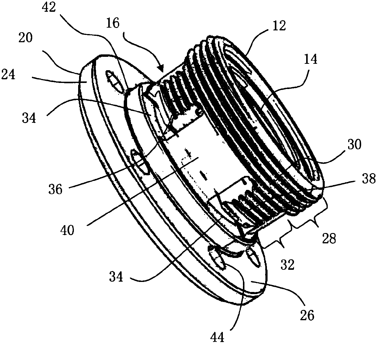
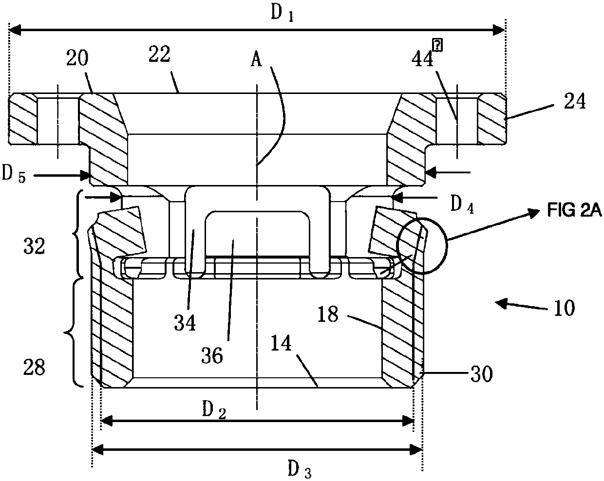
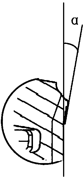
[0024] figure 1 and figure 2 shown for inserting into a threaded hole T ( image 3 ) of the insert 10 in the workpiece S. The insert 10 has an axis of rotation A and also includes a first end 12 defining a circular opening 14 , a cylindrical barrel 16 having an inner wall 18 and an outer wall, and a second end 20 defining a circular opening 22 . In another embodiment, the opening 22 may be non-circular, for example, in order to achieve the function of rotation. The barrel of the insert is used for inserting a shaft through the insert 10 . The inner wall 18 may be cylindrical, or may include a fool-proofing that matches the shape of the shaft. The second end is formed with an outer diameter of D 1 an enlarged flange 24 having a surface 26 towards the first end 12 for abutment against an element to be assembled and held on the workpiece, for example a bearing ring mounted on a rotating shaft . The outer diameter D of the flange 1 Greater than any other outer diameter o...


PUM


Abstract

The invention relates to an insert (10) comprising a first end (12) defining a circular opening (14), a cylindrical barrel (16) having an inner wall (18) and an outer wall, and A second end (20) defining an opening (22) and forming an enlarged flange (24), characterized in that the barrel includes a first portion ( 28), and a second portion (32) adjacent to the first portion, the second portion (32) comprising at least two cutouts (34) defining at least two axially extending flexible protrusions (36), each A protrusion has an external thread (38) and forms an angle (α) with the axis of the insert toward the outside of the cylinder. This insert is used for axial fixing of the outer ring of the bearing.

Description

technical field [0001] The invention relates to an external thread insert, which comprises a fastening means for preventing undesirable loosening of the insert after installation. This insert is mainly used to fix the bearing ring axially and maintain the position of the bearing ring. Background technique [0002] According to the European standard EN4399:2008, a metal ferrule with an externally threaded cylindrical body is known, comprising a plurality of flexible protrusions at one end thereof, which also have external threads and are folded outwards to Realize the tightening function. However, this type of ring cannot be used to assemble bearings with a diameter larger than that of the ring. [0003] Also known is a metal insert with an externally threaded cylindrical barrel comprising an enlarged flange at one end and a fastening sleeve made of polyimide material inserted into the outer contour of the barrel at the other end lock up. When the insert is installed on t...

Claims


Application Information

Patent Timeline
IPC IPC(8): F16B37/06
CPCF16B37/067F16C35/067F16B39/284F16B39/22F16B39/34F16C35/07
Inventor 阿兰·菲利普吉尔达斯·博雷斯
Owner LISI AEROSPACE
Why Eureka
Try Eureka