
Thread replacement system and device

a technology of thread replacement and thread insert, which is applied in the direction of threaded fasteners, screws, fastening means, etc., can solve the problems of difficulty in reassembling the device, the thread must be replaced, and the conventional thread insert has a tendency to loosen, etc., to achieve simple and inexpensive manufacturing, low thickness, and durable construction

Inactive Publication Date: 2002-05-07
LOCK N STITCH INC
View PDF3 Cites 26 Cited by
  • Summary
  • Abstract
  • Description
  • Claims
  • Application Information

AI Technical Summary

Benefits of technology

A further object of the present invention is to provide a thread-insert which permits the same thread as the original undamaged threads so as to avoid the complexities of different size fasteners needed to assemble and disassemble an object or objects.
Another further object of the present invention is to provide a thread-insert that avoids the tendency to become loose when disassembly is required by providing exterior threads that are upwardly slanted thread surfaces that angle upward toward the head of the thread-insert and lock the insert securely into the replacement hole of the object.
Another further object of the present invention is to provide a thread-insert wherein the exterior threads are slightly spaced from each other and maintain a minimum thickness between a root and a crest thereof, providing a durable thread.

Problems solved by technology

However, if the thread is damaged to such an extent that chasing with a tap will not restore its function, the thread must be replaced.
This is, at the very least inconvenient and may result in difficulty for those reassembling the device.
A conventional thread-insert has a tendency to become loose when the machine screw is removed for disassembly or, in some cases, the thread-insert will unscrew from the object when removal of the attaching screw is attempted thus complicating the disassembly process.
In addition, if the attaching screw must provide a sealed engagement with the object, a conventional thread-insert will not usually provide a seal between its external threads and the wall of the object.

Method used


Image

  • Thread replacement system and device
  • Thread replacement system and device
  • Thread replacement system and device

Examples


Embodiment Construction

Considering the drawings, wherein like reference numerals denote like parts throughout the various drawing figures, reference numeral 10 is directed to the preferred embodiment according to the present invention.

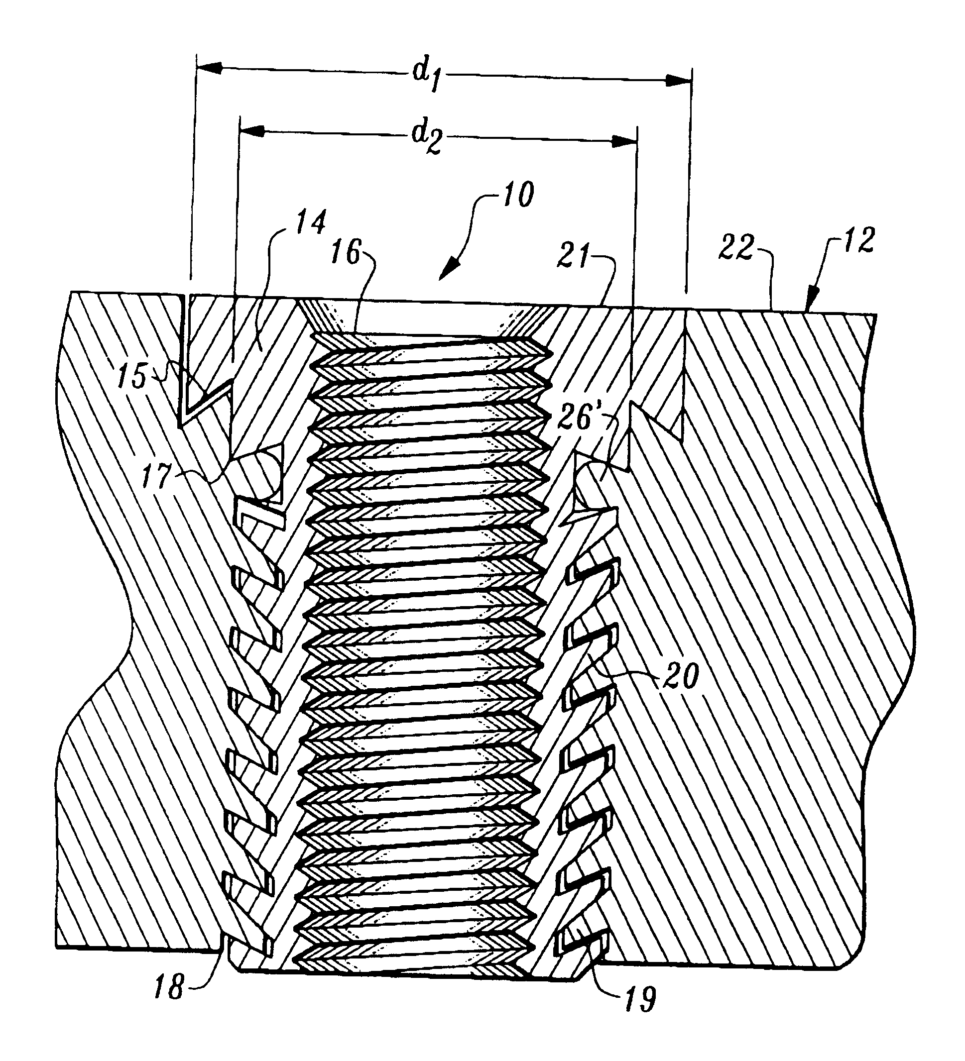
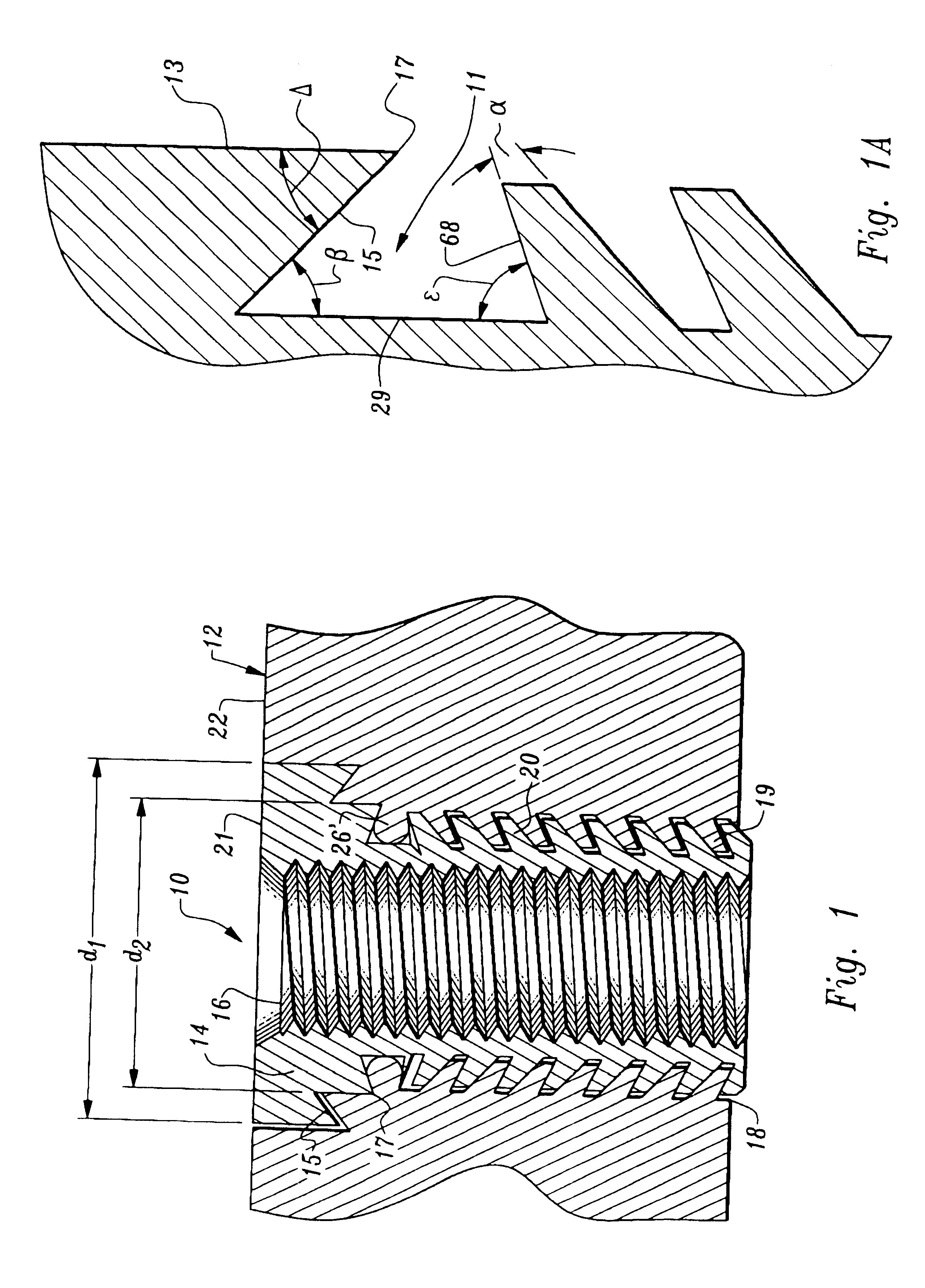
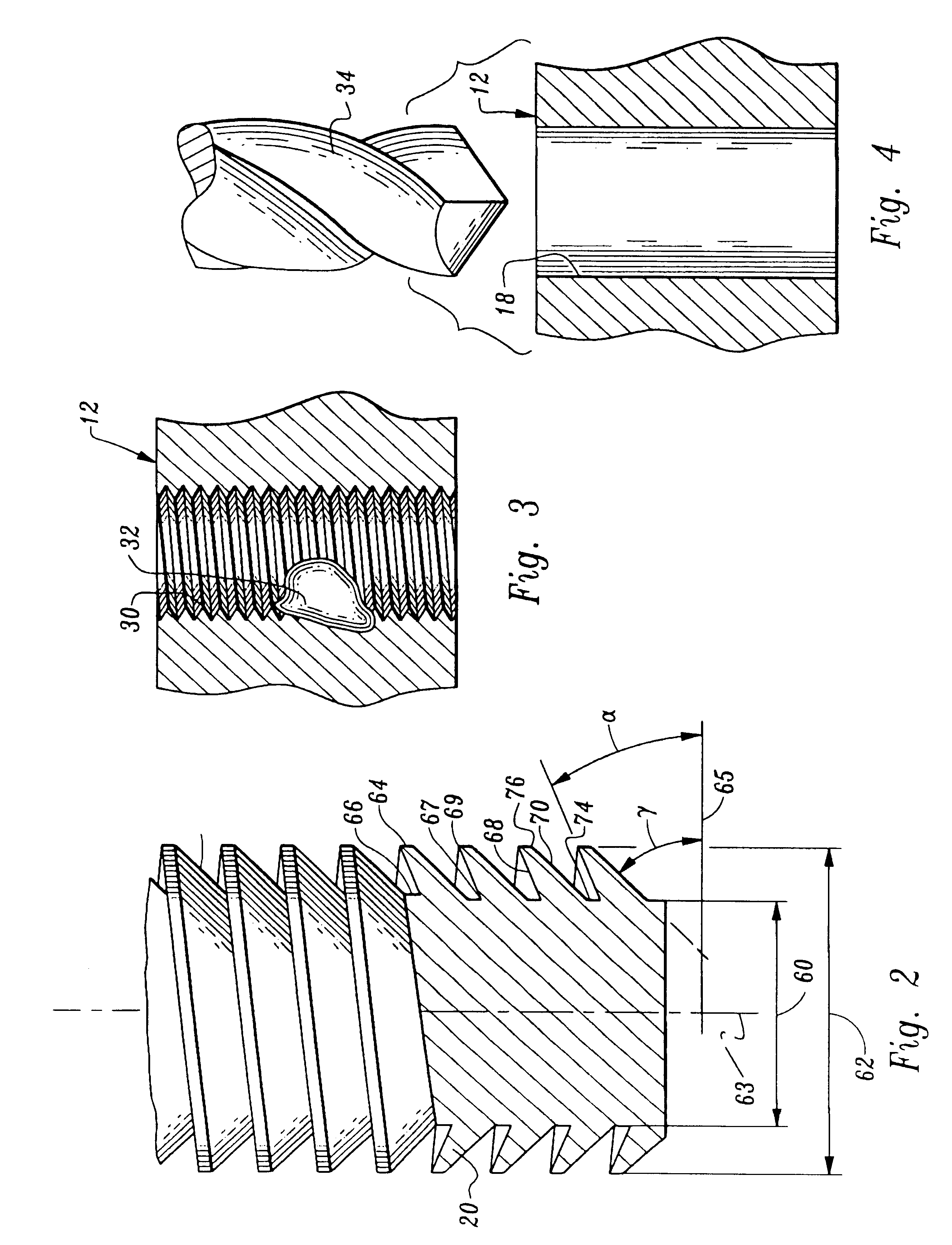
Referring to FIG. 1, there is illustrated one preferred embodiment of the thread-insert 10 after it has been fully installed in an object 12 to replace damaged threads 32 (FIG. 3) in a hole in the object. The object 12 can be any device which requires threaded holes for assembly with a second part or for attaching other devices to the object. A hole 18 (FIG. 4) has been bored with a drill 34 into the object 12 and matching threads 19 (FIG. 6) have been cut into the wall of the hole 18.

The thread-insert 10 may be rotated into the threaded hole of the object until the top surface 21 of the thread-insert 10 is substantially flush with the upper surface of the object 12. If the top surface 21 projects above the object 12, it may be left as is or ground flush. As can be seen in F...


PUM

PropertyMeasurementUnit
90° angleaaaaaaaaaa
included angleaaaaaaaaaa
angleaaaaaaaaaa

Abstract

The present invention relates to a system and device which allows the replacement of a damaged thread in an object with a thread identical to the damaged thread by enlarging the original threaded hole and inserting a thread-insert in a newly threaded hole in the object which has an internally threaded hole identical to the original threaded hole. The thread-insert is fastened into the enlarged hole using a thread that securely holds it in place. When the thread-insert is threaded into the enlarged threaded hole, a pocket formed below the drive head of the thread-insert causes metal flow into the pocket to create a seal between the thread-insert and the object.

Description

The following invention relates generally to a system and device for replacing damaged screw threads in an object, and in particular to a system and device for replacing damaged screw threads which will replace the threads with a permanently installed insert, the insert also provides a seal between the insert and the object to be repaired.When internal screw threads cut into an object become damaged, they can sometimes be repaired by chasing the damaged thread with a tap to restore the thread shape. However, if the thread is damaged to such an extent that chasing with a tap will not restore its function, the thread must be replaced. This can be done by boring out the original threads with a drill larger than the major diameter of the thread and rethreading the hole with a larger diameter thread. While this method will provide a usable threaded hole, it will require a fastener of a different size than the original. In an assembly which must be dissembled and reassembled periodically,...

Claims


Application Information

Patent Timeline
Patent Type & Authority Patents(United States)
IPC IPC(8): B23P6/04B23P6/00F16B37/12F16B37/00F16B33/00
CPCB23P6/04F16B37/125F16B33/004F16B39/282
Inventor REED, GARY J.
Owner LOCK N STITCH INC
Learn More