Continuous method of rolling a powder metallurgical metallic workpiece

a technology of powder metallurgical and workpiece, which is applied in the field of manufacturing of metallic products, can solve the problems of destructive evaluation process and non-destructive testing techniques, and achieve the effect of reducing the number of rolling steps

Inactive Publication Date: 2010-01-19
PHILIP MORRIS USA INC
View PDF59 Cites 23 Cited by
  • Summary
  • Abstract
  • Description
  • Claims
  • Application Information

AI Technical Summary

Benefits of technology

[0012]It is an object of the present invention to minimize the number of rolling steps required to reduce a workpiece by a minimum of 50% of its thickness.
[0015]An apparatus for rolling of a metallic workpiece is provided having a feeding device operable to convey the workpiece along the process line, a first induction heating apparatus in operable communication with a first RF generator and operable to heat the workpiece during movement along the process line, at least a first hot rolling mill and a process control device operable to monitor at least one parameter of the first FR generator. An optional second hot rolling mill with associated induction heating apparatus and RF generator can be included. A heating device in thermal communication with one or more surfaces of a roll of the first and / or second hot rolling mill can maintain the surface of the roll at a second temperature. Also, optionally, at least one cold rolling mill can be located downstream of a last hot rolling mill followed by a post-roll annealing apparatus having an annealing induction heating apparatus in operable communication with an annealing RF generator.

Problems solved by technology

Testing techniques may be non-destructive (i.e., ultrasonic examination) or may be destructive evaluation processes (i.e., sectioning and polishing for microscopic or visual examination).

Method used


Image

  • Continuous method of rolling a powder metallurgical metallic workpiece
  • Continuous method of rolling a powder metallurgical metallic workpiece
  • Continuous method of rolling a powder metallurgical metallic workpiece

Examples


Embodiment Construction

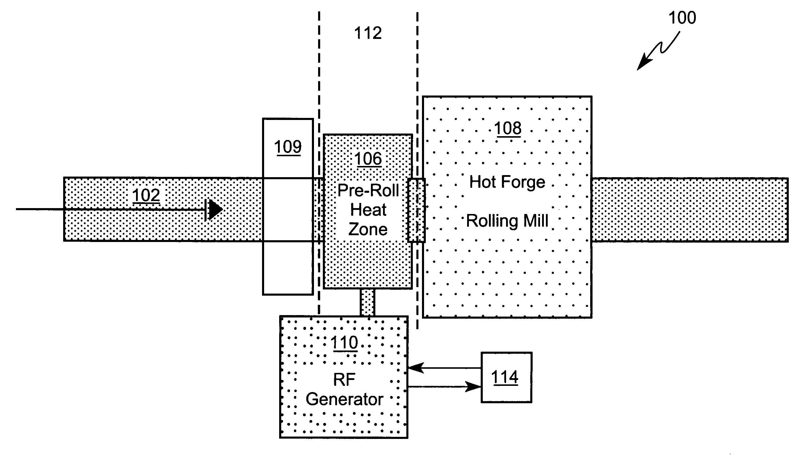
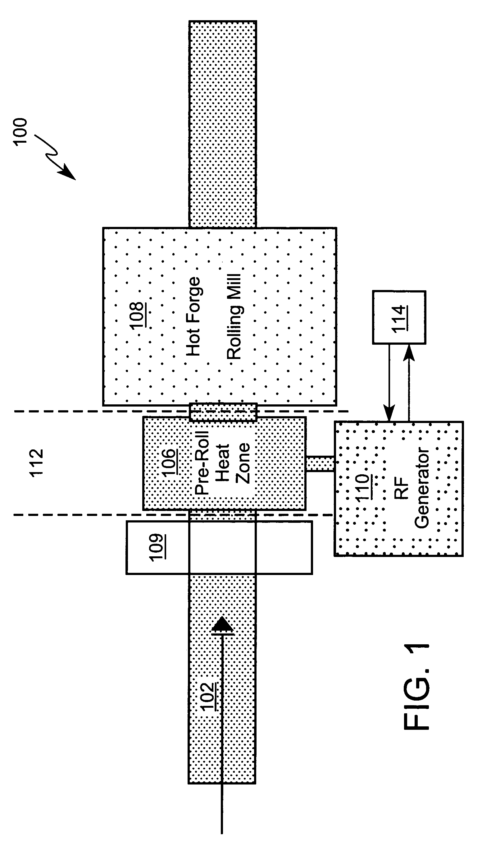
[0020]FIG. 1 is a schematic illustration of an embodiment of the layout of a hot rolling line 100 for the processing of an aluminide workpiece 102. A workpiece 102, such as sheet stock, can be fed into a feeding device 104 which outputs to a first induction heating apparatus 106. The heated workpiece 102 is then fed into a first hot rolling mill 108 for reduction in thickness. A first RF generator 110 in operable communication with the first induction heating apparatus 106 substantially constitutes a first induction heating zone 112.

[0021]The feeding device 104 can be any suitable device that can maintain the desired tension and lateral alignment on the workpiece 102. Alternatively, the feeding device 104 can be eliminated and a suitable feeding means can be employed to achieve the desired tension and lateral alignment, for example by a continuous feeding operation conducted from a tensioned bobbin. In a preferred embodiment, the feeding device 104 can be a pinch roll that operates ...


PUM

PropertyMeasurementUnit
speedaaaaaaaaaa
temperaturesaaaaaaaaaa
temperatureaaaaaaaaaa

Abstract

An apparatus for rolling of a powder metallurgical metallic workpiece is provided having a feeding device, a first induction heating apparatus in operable communication with a first RF generator and at least a first hot rolling mill. A process control device monitors at least one parameter of the first RF generator and outputs a signal. A method for continuous rolling of a metallic workpiece is also provided using the apparatus for rolling. The process control device signal can be used to monitor metallurgical properties of the workpiece and provide in-line evaluation of the workpiece.

Description

[0001]This is a Division of U.S. application Ser. No. 10 / 201,933, now U.S. Pat. 7,192,551, filed on Jul. 25, 2002, entitled INDUCTIVE HEATING PROCESS CONTROL OF CONTINUOUS CAST METALLIC SHEETS, the entire contents of which is incorporated by reference, and for which priority is claimed under 35 U.S.C. § 120.BACKGROUND[0002]1. Field of the Invention[0003]The invention is directed to the manufacture of metallic products such as sheet, strip, rod, wire or band, especially of difficult to work intermetallic alloys like aluminides of iron, nickel and titanium. Particularly, the invention is directed to a hot rolling operation utilizing an inductive heating processing step and associated process control feedback.[0004]2. Background of the Invention[0005]In the description of the background of the present invention that follows, reference is made to certain structures and methods, however, such references should not necessarily be construed as an admission that these structures and methods...

Claims


Application Information

Patent Timeline
Patent Type & Authority Patents(United States)
IPC IPC(8): B22F1/00B21B3/00B21B9/00B21B27/06B21B27/10B21B39/00B21B39/08B21B45/00B22F3/18C21D1/42C21D7/13
CPCB22F3/18B22F3/105B22F3/16B22F3/24B22F3/14C21D7/13B22F2999/00B22F2201/10B21B3/00B21B9/00B21B27/06B21B27/106B21B39/006B21B39/08B21B45/004B21B2045/006B22F2003/1053B22F2003/248B22F2998/10C21D1/42Y02P10/25
Inventor SHARPE, DAVIDRASOULI, FIROOZCUNNINGHAM, JOHN F.
Owner PHILIP MORRIS USA INC
Why Eureka
Try Eureka