Nonmetal rotating shaft convenient to power

A non-metallic and rotating shaft technology, applied in the field of nanofiber preparation, can solve the problems of affecting the electric field of the spinning emitter, energy waste, and affecting the spinning effect, so as to avoid the problem of wire winding, simple connection method, and reduce energy waste. Effect

Inactive Publication Date: 2016-11-16
TIANJIN POLYTECHNIC UNIV
View PDF5 Cites 0 Cited by
  • Summary
  • Abstract
  • Description
  • Claims
  • Application Information

AI Technical Summary

Problems solved by technology

At present, most of the rotating needle-free electrospinning devices are metal shafts. It is a common method to charge the electrospinning emitter by directly applying power to the metal shaft through a brush. However, the metal shaft is also charged Distribution, the generated electric field affects the electric field of the spinning emitter, and then affects the spinning effect, and at the same time, it will also cause energy waste

Method used


Image

  • Nonmetal rotating shaft convenient to power
  • Nonmetal rotating shaft convenient to power
  • Nonmetal rotating shaft convenient to power

Examples


Embodiment 1

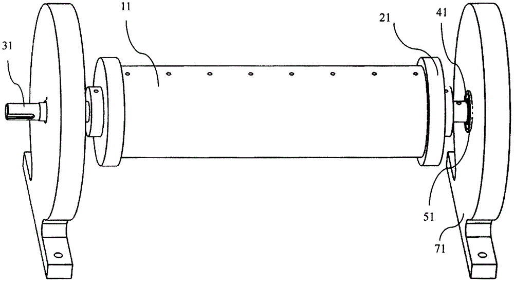
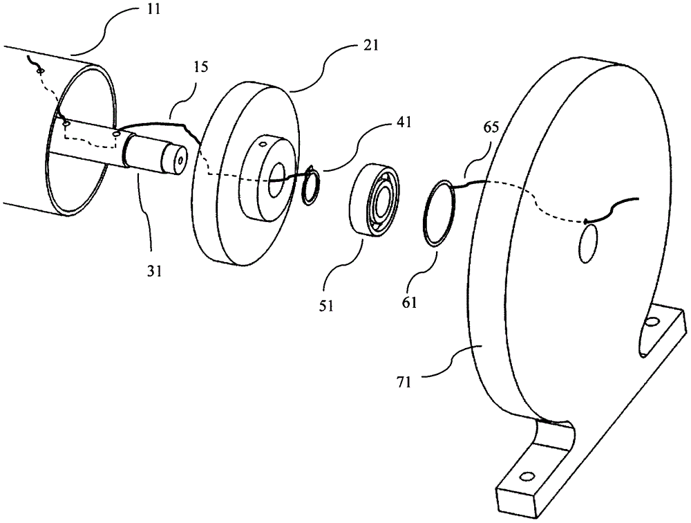
[0023] Electrospinning emits extremely discontinuous monomer structures such as Figure 4 As shown, it is specifically 8 disc-shaped electrospinning emitters 12 arranged at equal intervals, and then 8 small holes with a diameter of 3 mm are opened on the support sleeve 11 parallel to the axis, and are respectively connected with 8 circularly arranged at equal intervals. Corresponding to the disc-shaped electrospinning emitter 12, one end of the 8 metal wires is respectively connected to the disc-shaped electrospinning emitter 12, and then the 8 wires are respectively introduced into the support from the corresponding small holes on the support sleeve 11. Inside the casing 11, and twisted into a wire 15, it penetrates the central shaft 31 from the hole 1 on the central shaft 31, and is drawn out from the hole 2, and the wire 15 is tied to the circular hole of the snap ring 41; the fixed ring 61 Before installation, one end of a metal wire 65 is tied to the fixed ring 61, and th...

Embodiment 2

[0025] Electrospinning emits extremely continuous structures such as Figure 5As shown, it is specifically a helical blade type electrospinning emitter 13, and a small hole with a diameter of 3 mm is opened on the support sleeve 11 at a distance of 10 mm from the left end face of the end cover of the support sleeve at the right end, and one end of a metal wire is connected to the The spiral blade type electrospinning emitter 13 is connected, and the other end of the metal wire 15 is introduced into the support sleeve 11 from the corresponding small hole on the support sleeve 11, and penetrates the central shaft 31 from the hole 1 on the central shaft 31, Draw out from hole 2, and wire 15 is fastened in the round hole of jump ring 41; Described fixed ring 61 is before installation, and one end of a metal wire 65 is tied on the fixed ring 61, and the other end is from described bearing seat 71 bearing Pass through the small hole above the hole, and then install the fixed ring 61...


PUM

PropertyMeasurementUnit
diameteraaaaaaaaaa

Abstract

The invention relates to a nonmetal rotating shaft convenient to power, and belongs to the field of nanometer fiber preparation. The rotating shaft comprises a supporting sleeve, two supporting sleeve end covers, a center shaft, a clamping spring, a bearing, a fixing ring and a bearing pedestal. The supporting sleeve is sleeved with an electrostatic spinning emitting electrode. The supporting sleeve and the two supporting sleeve end covers form a whole. One end of a wire is connected with the electrostatic spinning emitting electrode, and the other end of the wire penetrates into the center shaft from a small hole in the supporting sleeve, is led out from the small hole close to the end face of the center shaft and is tied to the clamping spring. The other metal wire is tied to the fixing ring, and the other end penetrates out from a small hole of the bearing pedestal, then, the fixing ring is installed on the matching face of a bearing and the bearing pedestal. In this way, an electrode of a direct current voltage power source is clamped to the wire penetrating out from the bearing pedestal, and voltage can be conveniently transmitted to the electrostatic spinning emitting electrode. Influences and energy waste on an electric field can be effectively lowered, and the problem that wires are wound is effectively avoided.

Description

technical field [0001] The invention relates to a non-metallic rotating shaft convenient for electrification, in particular to a non-metallic rotating shaft used for a rotary needleless electrospinning emitter, and belongs to the field of nanofiber preparation. Background technique [0002] In a narrow sense, nanofibers refer to fibers with a diameter of less than 100nm. They have the characteristics of large specific surface area and high porosity, and are widely used in high-efficiency filtration materials, wound dressings, tissue engineering, composite materials, battery electrodes, and micro-nano devices. [0003] Electrospinning is a method of preparing nanofibers by stretching a polymer solution or melt by an electric field force generated by a high-voltage DC power supply, and is one of the most effective techniques for preparing nanofibers. At present, there are two main types of electrospinning technologies used for mass production of nanofibers, namely, multi-needl...

Claims


Application Information

Patent Timeline
Patent Type & Authority Applications(China)
IPC IPC(8): D01D5/00
CPCD01D5/0092
Inventor 刘健刘延波蒋秀明刘宝刘泳汝
Owner TIANJIN POLYTECHNIC UNIV
Why Eureka
Try Eureka