Underground diaphragm wall groove segment slurry taking device
A technology for underground diaphragm walls and grooves, which is used in sheet pile walls, foundation structure testing, construction, etc., can solve problems such as uneven arrangement, unfavorable movement, winding of measuring ropes, etc., and achieves accurate detection depth and convenient flexible movement. Effect
Active Publication Date: 2016-11-16
SHANGHAI FOUND ENG GRP
View PDF7 Cites 8 Cited by
- Summary
- Abstract
- Description
- Claims
- Application Information
AI Technical Summary
Problems solved by technology
The manual portable slurry extraction method is often used in shallower underground diaphragm wall projects and extraction of slurry in the mud box due to the danger of the slurry extraction process, inaccurate slurry extraction depth, and time-consuming and laborious operation.
Although the simple pulp extractor is improved on the basis of the traditional hand-held pulp extraction method, there are still some problems: the installation of the device is cumbersome, which is not conducive to transportation and on-site assembly, and it can only be scrapped when the equipment is damaged; the opening angle of the device bracket is fixed , can not be applied to the underground diaphragm wall project with a variety of slot widths; the overall weight of the device is relatively large, which is not conducive to movement; the measurement depth of the slurry extraction
Method used
View moreImage
Smart ImageViewing Examples

Examples
 PUM
 Abstract
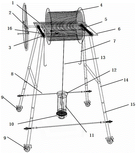
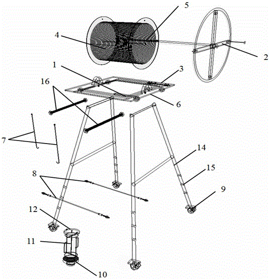
The invention relates to an underground diaphragm wall groove segment slurry taking device. The underground diaphragm wall groove segment slurry taking device comprises a circle counter, a rocker, positioning plugs, a winding reel, a wire pressing pole, a bracket, hooks, a support, limiting holes and a bolt, wherein fixable movable trundles are arranged at the bottom of the support, are in fit connection with the limiting holes in the support through limiting rods and are used for adjusting the opening angle of the support and keeping the slurry taking device to be wholly stable; the support is fixed below the bracket through the bolt; the winding reel is connected with the rocker and arranged on the bracket; a steel wire rope is wound on the winding reel and penetrates through a top cover of a slurry taking barrel and a slurry taking barrel body to be connected with a bottom board of the slurry taking barrel; the hooks are arranged on the lower portion of the bracket; and the positioning plugs and the circle counter are arranged on the upper portion of the bracket. The problems that an existing slurry taking device is difficult to move, combination and assembly are complex, the opening degree of a support is unchangeable, the support is difficult to fix, a slurry taking barrel is put down and lifted with much time and effort, and the slurry taking position is inaccurate as a measurement rope is abraded are solved, and on-site slurry taking safety and high efficiency at any deep position inside a construction groove segment of an underground diaphragm wall are achieved.
Description
technical field [0001] The invention relates to a slurry extraction device for building construction, in particular to a slurry extraction device for the slurry in the groove section of an underground continuous wall. Background technique [0002] The underground diaphragm wall is a kind of trenching machine used on the ground for foundation engineering. Under the condition of mud retaining wall, deep grooves are excavated along the peripheral axis of the deep excavation project. After the grooves are cleaned, steel cages are hung in the grooves, and then Conduit method is used to pour underwater concrete to form a unit trough section, which is carried out section by section, and a continuous reinforced concrete wall is built underground as a water interception, seepage prevention, load bearing, and water retaining structure. It has the characteristics of small construction vibration, high wall rigidity, good integrity, fast construction speed, earth and stone saving, deep f...
Claims
Login to View More Application Information
Patent Timeline
 IPC IPC(8): E02D5/18E02D33/00
CPCE02D5/187E02D33/00
Inventor 罗云峰王佳杰袁芬李耀良张云海张哲彬王理想孙睿黄周琰
Owner SHANGHAI FOUND ENG GRP
Features
- R&D
- Intellectual Property
- Life Sciences
- Materials
- Tech Scout
- Unparalleled Data Quality
- Higher Quality Content
- 60% Fewer Hallucinations
Learn More Browse by: Latest US Patents, China's latest patents, Technical Efficacy Thesaurus, Application Domain, Technology Topic, Popular Technical Reports.
© 2025 PatSnap. All rights reserved.Legal|Privacy policy|Modern Slavery Act Transparency Statement|Sitemap|About US| Contact US: help@patsnap.com