Smart home safe guard system and control method thereof

A security system and smart home technology, applied in the direction of alarms, instruments, etc., can solve the problems of not being able to effectively avoid global paralysis, complicated wiring, high operation and maintenance costs, achieve tailorability and anti-interference ability enhancement, and simplify system debugging The process, debugging and maintenance are simple and convenient

Active Publication Date: 2016-02-17
QUFU NORMAL UNIV
View PDF6 Cites 29 Cited by
  • Summary
  • Abstract
  • Description
  • Claims
  • Application Information

AI Technical Summary

Problems solved by technology

[0004] (1) The wiring is complex and the installation space is large
[0005] (2) The amount of cables is large, wasting materials
[0006] (3) The system has fixed functions and poor scalability
[0007] (4) High operation and maintenance costs and energy loss
[0008] (5) The mobile performance is poor and affects the appearance
[0009] (6) The stability of the system is relatively low, and it cannot effectively avoid the situation of global paralysis caused by the failure of the central system

Method used


Image

  • Smart home safe guard system and control method thereof
  • Smart home safe guard system and control method thereof

Examples


Embodiment 1

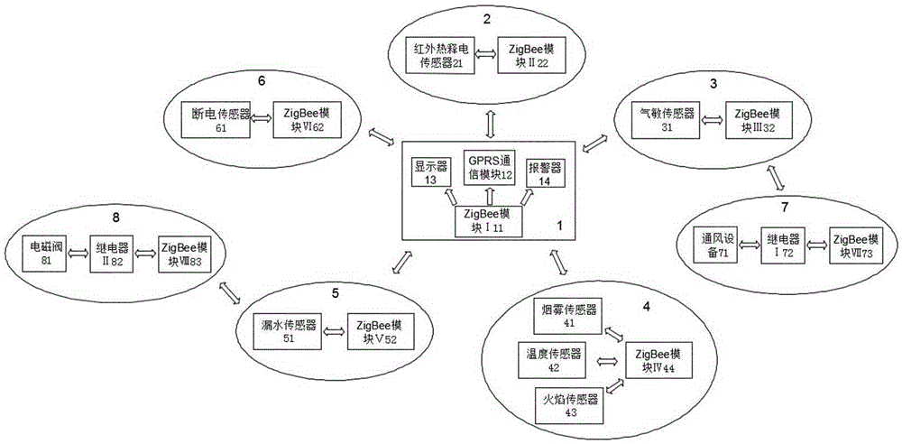
[0038] Such as figure 1As shown, the smart home security system of the present invention includes an alarm subsystem 1 and several monitoring subsystems, and the alarm subsystem 1 includes a ZigBee module I 11 and a GPRS communication module 12, a display 13, Alarm 14 and UPS power supply module 15, described GPRS communication module 12 is used for sending short messages to user's mobile phone, and UPS power supply module 15 is used for continuing to supply power for the system for a period of time when a power outage occurs, ensuring that the power outage information can be sent to the user's mobile phone . The monitoring subsystem includes the anti-theft monitoring subsystem 2, the gas leakage monitoring subsystem 3, the fire monitoring subsystem 4, the water leakage monitoring subsystem 5 and the power failure monitoring subsystem 6, and the gas leakage monitoring subsystem 3 and the water leakage monitoring subsystem 5 also have Linkage subsystems that can prevent the d...

Embodiment 2

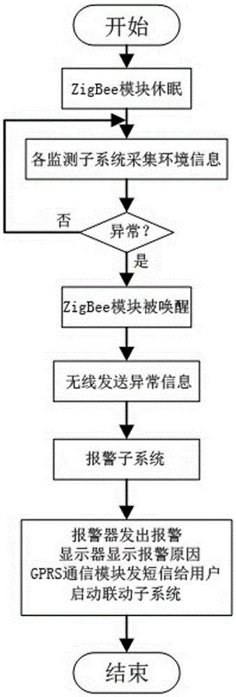
[0046] Such as figure 2 As shown, a control method of a smart home security system as described in Embodiment 1, comprising the following steps:

[0047] S1, the system is turned on, and the ZigBee modules in the alarm subsystem 1, each monitoring subsystem and each linkage subsystem are in a dormant state;

[0048] S2. The monitoring sensors of each monitoring subsystem collect environmental information in real time;

[0049] S3, the ZigBee module in each monitoring subsystem judges whether the information collected by the monitoring sensor is abnormal, if there is abnormality, proceed to the next step; if there is no abnormality, return to step S2;

[0050] S4. The ZigBee module in the monitoring subsystem where the abnormal information is located and the ZigBee module I11 in the alarm subsystem 1 are awakened. If the monitoring subsystem where the abnormal information is located is connected to a linkage subsystem, the ZigBee module in the linkage subsystem is also activa...


PUM


Abstract

The invention discloses a smart home safe guard system. The smart home safe guard system comprises an alarm subsystem and multiple monitoring subsystems. The alarm subsystem comprises a ZigBee module I and a GPRS communication module, a display and an alerter which are connected with an output end of the ZigBee module I, each monitoring subsystem is internally provided with a monitoring sensor and a ZigBee module, and each monitoring subsystem is in communication connection with the ZigBee module I of the alarm subsystem through the corresponding ZigBee module in the corresponding system. According to the safe guard system, wireless automatic networking can be achieved, debugging and maintenance are easy, convenient and rapid, the cost performance is high, installation is easy, the space is saved, attractiveness is achieved, real-time monitoring of various home environments can be achieved, the good home environment is guaranteed, the stability of the system is high, and the situation of global paralysis caused by failure of a central control system can be effectively avoided.

Description

technical field [0001] The invention relates to a smart home security system and a control method thereof, belonging to the technical field of security. Background technique [0002] In the field of information technology in China, with the continuous improvement of people's living standards and the arrival of the post-PC era, people's requirements for property and personal safety are also getting higher and higher, so home security systems have emerged. The function of the home security system involves a higher level of improvement rather than being limited to anti-theft, fire prevention, air leakage prevention, and water leakage prevention. It has extremely important practical guiding significance for improving the living standards of contemporary people and ensuring social security. [0003] Although the development of home security system-related products is relatively mature, almost all products focus on the use of the central control system to control the operation of...

Claims


Application Information

Patent Timeline
Patent Type & Authority Applications(China)
IPC IPC(8): G08B19/00G08B25/10
CPCG08B19/00G08B25/10
Inventor 李光顺禹继国吴俊华成秀珍孔令增刘华张伟李申
Owner QUFU NORMAL UNIV
Why Eureka
Try Eureka