A signal generator and method for using the same to test cable faults

A technology of cable fault and testing method, applied in the direction of fault location, etc., can solve the problems of long fixed-point time, low efficiency, high labor intensity, etc., and achieve the effect of stable operation and high safety of equipment

Active Publication Date: 2019-10-11
淄博信易杰电气有限公司
View PDF9 Cites 0 Cited by
  • Summary
  • Abstract
  • Description
  • Claims
  • Application Information

AI Technical Summary

Problems solved by technology

[0003] The principle of cable fault test vehicle detection is to increase the detection efficiency by increasing the discharge energy, but the equipment is heavy and can only be transferred by vehicle, which is very limited for some areas where the terrain or roads are restricted.
For the portable fault tester, the method of reducing the discharge energy is adopted, and its disadvantage is that it is difficult to measure the distance of some faults and it is difficult to fix the point.
[0004] Throughout the domestic and foreign cable fault testers and cable fault test vehicles, the fixed point method of manual on-site monitoring is adopted when the cable fault is fixed. The environment is poor, the labor intensity is high, the pressure is high, and the requirements for on-site personnel are high. It is really the bottleneck of cable fault testing.

Method used


Image

  • A signal generator and method for using the same to test cable faults
  • A signal generator and method for using the same to test cable faults
  • A signal generator and method for using the same to test cable faults

Examples


Embodiment Construction

[0032] The following will clearly and completely describe the technical solutions in the embodiments of the present invention with reference to the accompanying drawings in the embodiments of the present invention. Obviously, the described embodiments are only some, not all, embodiments of the present invention. Based on the embodiments of the present invention, all other embodiments obtained by persons of ordinary skill in the art without creative efforts fall within the protection scope of the present invention.

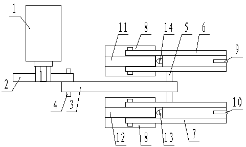
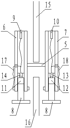
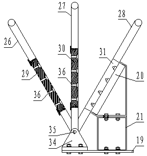
[0033] Such as figure 1 , 2 , 3, 4, and 5 shown, the utility model comprises a high voltage source, a discharge device and a capacitance wiring conversion device.

[0034] The capacitive connection conversion device includes a bottom plate 19 , a capacitor connection plate 20 arranged above the bottom plate 19 and a capacitive connection conversion mechanism. A base 21 is affixed to the upper surface of the bottom plate 19 , and the capacitor wiring board 20 is a...


PUM


Abstract

The invention relates to a high-voltage signal generator which comprises the components of a high-voltage source, an electric discharging device and a capacitive wiring conversion device. The capacitive wiring conversion device comprises a base board, a capacitive wiring board and a capacitive wiring conversion mechanism, wherein the capacitive wiring board and the capacitive wiring conversion mechanism are arranged above the base board. The capacitive wiring conversion mechanism comprises a serial wiring module, a parallel wiring module and a serial-parallel wiring module. The electric discharging device comprises a swing rod charging / discharging mechanism and a driving mechanism which drives the swing rod charging / discharging mechanism to swing. The swing rod charging / discharging mechanism comprises an anode swing rod, a cathode swing rod, a charging wiring board and an insulating baffle board. The insulating baffle board is arranged between the anode swing rod and the cathode swing rod. The invention further relates to a method for performing cable fault testing through the high-voltage signal generator. Compared with the prior art, the high-voltage signal generator is advantageous in that a charging operation is totally separated from a discharging operation in the charging process and the discharging process; the charging process and the discharging process are individually performed; a cross influence is prevented; and high operation stability of the whole equipment is ensured.

Description

technical field [0001] The invention relates to a signal generator and also relates to a method for using the generator to perform cable fault testing. Background technique [0002] In the past ten years, the domestic construction has developed greatly, and the amount of cables has begun to expand rapidly. Especially in recent years, many cities have implemented overhead lines into the ground for the sake of urban beauty, and a large number of cables have been used, which puts forward challenges for the operation and maintenance of cables. higher requirement. Moreover, due to the diversification of customers and different levels of demand, the original single demand of power supply system has developed into the direction of multi-industry and multi-level demand. For example, in the power supply system, the cables selected by users are getting longer and longer, and the cross-sectional area is getting larger and larger. The required tester requires a larger capacity. For som...

Claims


Application Information

Patent Timeline
Patent Type & Authority Patents(China)
IPC IPC(8): G01R31/08
Inventor 张延辉
Owner 淄博信易杰电气有限公司
Why Eureka
Try Eureka