Power adaptor

A technology of adapters and electric power, applied in the direction of test/measurement connectors, transformer/coil connectors, connections, etc., can solve problems such as high voltage of current transformer terminals, safety accidents, safety accidents of forgetting to short-circuit current transformers, etc.

Active Publication Date: 2016-11-16
STATE GRID CORP OF CHINA +4
View PDF5 Cites 12 Cited by
  • Summary
  • Abstract
  • Description
  • Claims
  • Application Information

AI Technical Summary

Problems solved by technology

[0003] The structure of the existing current transformer is basically the structure of iron core and winding. Therefore, in the process of electrification induction, the magnetic field is induced through the primary winding and then passed to the secondary winding through the magnetic field of the iron core, and then passed through the secondary winding. The secondary winding induces the converted current output, so in the working process of the current transformer, it must be operated in a short-circuit state, otherwise a high voltage will be generated on the terminals of the current transformer, which will easily cause a safety accident, while the existing The connection between the current transformer and the detection equipment is realized by the cooperation between the cable and the adapter. If the current transformer is powered on during the wiring process, the current transformer needs to be connected every time it is disassembled. It is very troublesome if the transformer is short-circuited and then not short-circuited, and it is easy to cause safety accidents caused by forgetting to short-circuit the current transformer

Method used


Image

  • Power adaptor
  • Power adaptor
  • Power adaptor

Examples


Embodiment approach

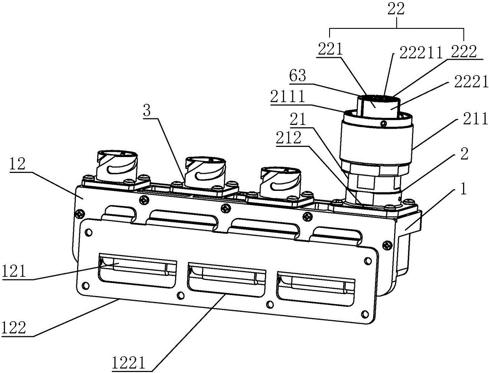
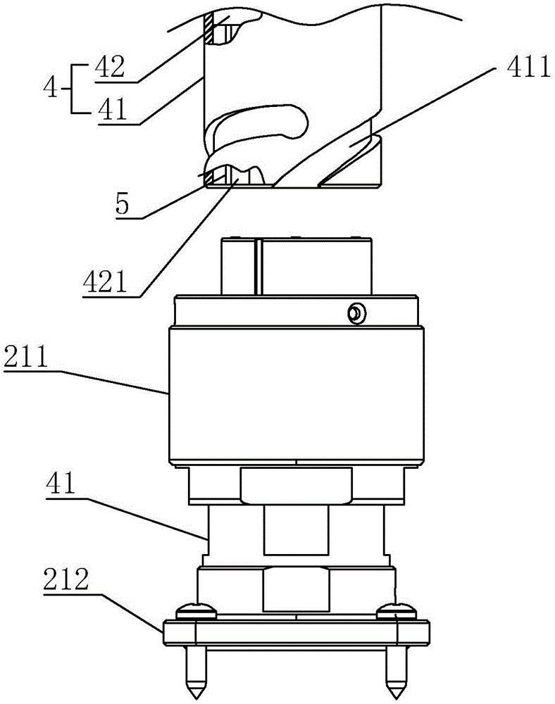
[0019] As an improved specific embodiment, the side of the female housing 21 facing the base 1 is fixedly connected with a connecting plate 212, the connecting plate 212 is square, and four fixing holes are respectively opened at positions close to the four corners. Four screws are used to pass through the four fixing holes to fix the connecting plate 212 to the base 1. The connecting plate 212 is also provided with a lock mark. By setting the connecting plate 212, the female head can be effectively realized by screws. The housing 21 is fixed to the base 1.

[0020] As an improved specific embodiment, a fixing plate 12 is fixedly connected to one side of the base 1, and a clamping plate 121 protruding outward is provided on one side of the fixing plate 12. The long plate 122 fixed with the external wall by screws is clamped. Through the setting of the clamping plate 121 and the long plate 122, the adaptor can be fixed to the external wall simply, quickly and effectively. Detacha...


PUM


Abstract

The invention discloses a power adaptor. The power adaptor comprises a base, a main connector and a plurality of secondary connectors, wherein the main connector and the plurality of secondary connectors are all arranged on the base, a female connector comprises a female head shell and a wiring structure, the wiring structure is arranged in the female head shell, the female head shell is fixed on the base by a screw, the wiring structure comprises a shell and a conductive assembly, the conductive assembly is inserted in the shell and is connected with the plurality of secondary connectors separately through wires, the conductive assembly comprises a fixed post and a plurality of conductive rods, the plurality of conductive rods are embedded in the fixed post, and a short-circuit structure is arranged in the fixed post and is used for enabling adjacent conductive rods to be short-circuited. In the power adaptor disclosed by the invention, a plurality of current transformers can be effectively connected to a detection device with the arrangement of the main connector and the secondary connectors; and with the arrangement of the short-circuit structure, the problem of a safety accident caused by open circuit occurring in the current transformers during the plug-in and plug-out process of the current transformers can be prevented.

Description

Technical field [0001] The present invention relates to a connecting device, and more specifically to a power adapter. Background technique [0002] Current transformers are widely used in various power equipment, and are mainly used for current conversion to achieve the purpose of detecting large currents. [0003] The current transformer structure is basically the structure of iron core and winding, so in the process of energization induction, the magnetic field is induced through the primary winding and then transferred to the secondary winding through the magnetic field of the iron core, and then through the secondary winding. The secondary winding induces the converted current output. Therefore, during the working process of the current transformer, it must be operated in a short-circuit state, otherwise high voltage will be generated on the terminals of the current transformer, which will easily cause safety accidents. The connection between the current transformer and the d...

Claims


Application Information

Patent Timeline
Patent Type & Authority Applications(China)
IPC IPC(8): H01R31/08H01R29/00H01R13/24H01R13/46
CPCH01R13/24H01R13/46H01R29/00H01R31/08H01R2201/20H01R2201/22
Inventor 蔡明珺王和忠王瑜林群杨雷郑圣南隆斯捷潘如海郑贤舜李泾陈韶村叶洪戴瑞海李小松陈海宏张克余一吴旭光杜志婕余正律王星洁汤耀景赵乐冰王诚杨欣谢郴恒任建成曾向朕
Owner STATE GRID CORP OF CHINA
Why Eureka
Try Eureka