Method for fixing chilling block on die slope

A technology of cold iron and inclined plane, which is applied in the direction of manufacturing tools, casting molding equipment, casting molds, etc., and can solve problems such as difficulty in mold removal, unfavorable post-production, magnetization of metal mold cold iron, etc.

Active Publication Date: 2016-11-23
KOCEL EQUIP
5 Cites 1 Cited by

AI-Extracted Technical Summary

Problems solved by technology

[0003] In the prior art, magnets are generally used to position the cold iron. This method is only suitable for metal molds and the cold iron is light in weight.
However, for heavy cold iron or wooden molds, the lack of magnetic force will cause the cold iron to shift ...

Method used

In this step, by accurately drawing the imprint of the cold iron position, it can be ensured that the subsequent sequence accurately puts the cold iron position. (D) Two capless steel nails 3 are fixed on both sides of the lower edge of the cold iron imprint relative to the center of gravity of the cold iron to support the cold iron, and the length of the capless steel nails 3 exposed to the surface of the mold slope 2 is 2— 3mm; in this step, by fixing the capless steel nail 3 on the lower edge of the position where the cold iron 2 is placed, the position of the cold iron 2 can be fixed during sand filling and vibration, thereby preventing the cold iron from sliding down...

Abstract

The invention relates to the technical field of casting, in particular to a method for fixing a chilling block on a die slope. The method particularly relates to the steps that (A) the thickness a of the chilling block is determined according to the casting thermal center or wall thickness size corresponding to the die slope; (B) the angle alpha between the die slope and the horizontal direction is measured, and the slope of the length b of the chilling block is determined according to a formula (1), a formula (2) and a formula (3), and please see the formula (1), the formula (2) and the formula (3) in the specification; (C) according to the length, determined in the last step, of the chilling block, a mark at the position of the chilling block is drawn at the design position of the chilling block, a paint mark with the good coating performance is sprayed; (D) two cap-free steel nails for fixing the chilling block are fixed at the positions, on the two sides relative to the line of the center of gravity of the chilling block, of the lower edge line of the mark of the chilling block; and (E) before modeling, the chilling block is placed according to the mark of the chilling block, a sand mixer is started to flow sand, a sand model is drawn after the sand model is compacted, a coating is applied to the surface of a cavity of the sand model, holes left by protruding parts of the steel nails on the surface of the cavity are covered and leveled, and the follow-up technological processes are executed.

Application Domain

Foundry mouldsFoundry cores +1

Technology Topic

GravitationMaterials science +3

Image

  • Method for fixing chilling block on die slope

Examples

  • Experimental program(1)

Example Embodiment

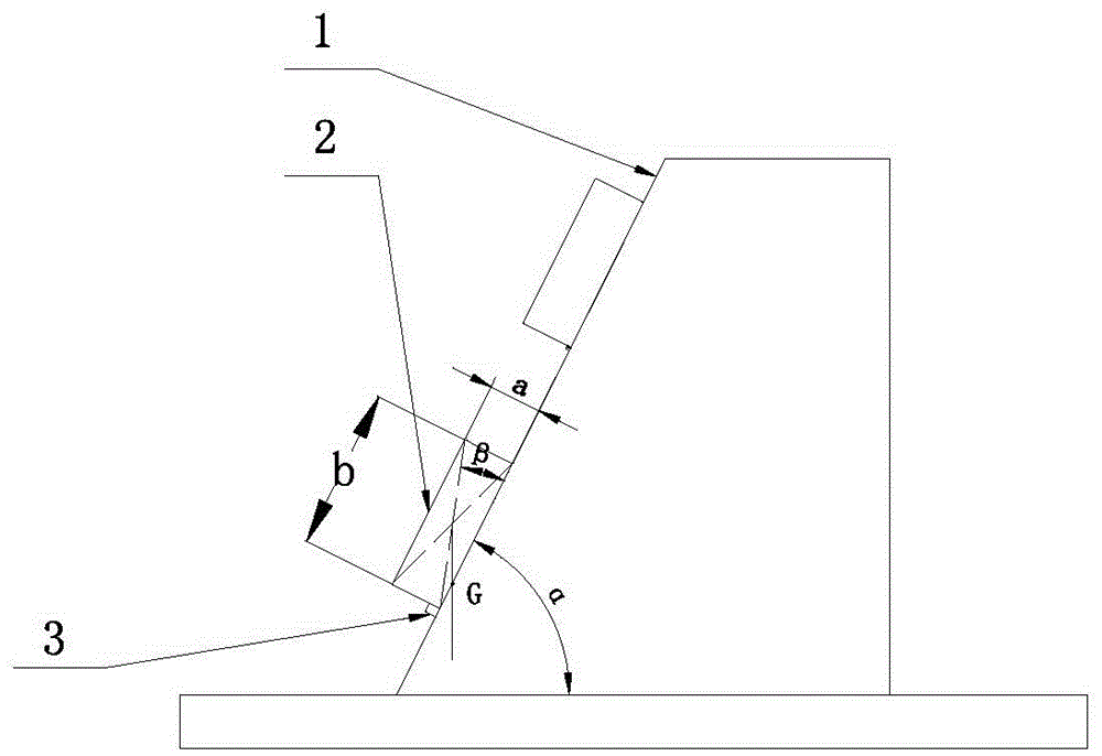
[0020] Such as figure 1 As shown, (A) First, according to the requirements of the casting structure, it is necessary to set the chilled iron 2 on the inclined surface 1 of the mold. According to the wall thickness of the casting at the inclined surface and the size of the hot section, determine the thickness of the chilled iron to be placed on the inclined surface as a, The value of a is 0.6-0.8 times the size of the hot joint of the casting. (B) Then measure the angle α between the inclined surface of the mold 1 and the horizontal direction, and determine the minimum length of the cold iron length b according to formulas (1), (2), and (3):
[0021] Formula 1),
[0022] Formula (2),
[0023] Formula (3);
[0024] Using the above method, the designed minimum length dimension of the chilled iron can make the intersection point of the center of gravity line of the chilled iron 2 and the placed mold slope 1 fall within the surface where the bottom surface of the chilled iron overlaps with the placed mold slope, thus Improve the stability of placing the cold iron on the inclined surface of the mold. (C) According to the length of the cold iron determined in step (B), draw the imprint of the cold iron position at the design position of the cold iron, and spray paint with reliable coating performance; in this step, apply the paint in two times, The first pass uses penetrating paint, the Baume degree is 0-60; the second pass uses the surface type paint, the Baume degree is 45-55.
[0025] In this step, by accurately drawing the imprint of the position of the cold iron, it can ensure that the position of the cold iron is accurately placed in the subsequent sequence. (D) Fix two capless steel nails 3 on both sides of the lower edge of the cold iron imprint relative to the center of gravity of the cold iron to hold the cold iron. The capless steel nails 3 are exposed to the surface of the inclined surface 2 of the mold with a length of 2— 3mm; In this step, by fixing the capless steel nails 3 on the lower edge of the position where the cold iron 2 is placed, the position of the cold iron 2 can be fixed in the sand filling vibration real time, thereby preventing the cold iron from sliding down the slope. (E) Before molding the core production, place the cold iron 2 according to the cold iron imprint, and then start the sand mixer to move the sand. After the sand is compacted, the sand mold is removed, paint is applied to the surface of the sand mold cavity, and the steel nail protrusions The holes left on the surface of the cavity are covered and smoothed, and then the subsequent process flow is performed. In this step, after the mold is released, the holes left by the capless steel nails on the surface of the cavity of the sand mold are covered and smoothed with paint to eliminate the influence of the steel nails on the cavity.

PUM

no PUM

Description & Claims & Application Information

We can also present the details of the Description, Claims and Application information to help users get a comprehensive understanding of the technical details of the patent, such as background art, summary of invention, brief description of drawings, description of embodiments, and other original content. On the other hand, users can also determine the specific scope of protection of the technology through the list of claims; as well as understand the changes in the life cycle of the technology with the presentation of the patent timeline. Login to view more.
Why Eureka
Try Eureka