Magnetic levitation stirring devices and machines for mixing in vessels

a stirring device and magnetic levitation technology, which is applied in the direction of material analysis through optical means, instruments, transportation and packaging, etc., can solve the problems of difficult aeration, inability to adequately resuspension, particulates, etc., to increase the liquid surface area, stir and aerate tall columns of liquids with ease, and increase the effect of liquid surface area

Inactive Publication Date: 2002-03-19
V & P SCI
View PDF6 Cites 183 Cited by
  • Summary
  • Abstract
  • Description
  • Claims
  • Application Information

AI Technical Summary

Benefits of technology

Thus it is the object of the method, devices and machines to provide a very simple process of uniformly mixing and aerating the contents of thousands of vessels, vials, test tubes and deep well microplates. We have made stainless steel magnetic stir balls, discs, bars, and dowels of different dimensions, shapes so that they will fit into any vessel and provide a vigorous stirring action when they are levitated by a magnetic field, then dropped by gravity or pulled down by the same or another magnetic field. By making the magnetic stirrers nearly the same diameter or length as the diameter of the vessel they are stirring or by putting multiple magnetic stirrers into a single vessel, a very significant stirring action is effected when they levitate up and down through the liquid. When the stirrers are levitated through the liquid meniscus it significantly increases the liquid's surface area and therefor increases aeration. We have discovered that while stainless steel is commonly thought to be non-magnetic, several stainless steels that have been "hardened", "spring tempered" or "cold worked," are magnetic. Because stainless steel is corrosion resistant, it maybe used as a magnetic stirrer without any protective coating, like teflon, thus making stainless steel magnetic stirrers very inexpensive.
Magnetic levitation stirring is produced by placing the vessel with the stirrers in the middle of a strong laterally focused magnetic field. Thus the stirrers are pulled to the wall of the vessel and raised to the height of the center of the magnetic field. By raising or lowering the vessel or the magnetic field one can move the stirrers up and down within the vessel. You can also raise and lower the stirrers by moving the vessels laterally through a focused magnetic field or moving the magnetic field laterally past the vessels. This lateral movement method relies on gravity to pull the stirrers down to the bottom of the vessel after the vessel passes through the magnetic field. In cases where the liquid is viscous, a magnet located along the path of lateral movement but below the vessel may be used to "pull" the stirrers to the bottom of the vessel. Magnetic levitation has the advantage of being able to stir and aerate tall columns of liquids with ease as it can be effected by simple vertical or lateral motion of either the vessel or the magnetic field.
It is also the object of the machines, device and method to provide a robust, economical and practical mixing method to resuspend particulates, to dissolve a solid in a liquid, to mix two or more liquid reagents, to emulsify two or more liquids, to break up aggregates, break up filamentous organisms, stimulate the growth of microorganisms, break open cells, or to mix and immobilize magnetic beads in vessels or microplate wells. The positive physical displacement of the liquid and particles by the levitation action of the stirrer produces a robust mixing or movement of the liquids and solids in the well. In the case where extracts are dried in the bottom of wells to be later suspended, the direct physical contact between the stirrer and the extract is often critical in the dissolving of the extract. Physical contact is also important in mixing oil and water to make an emulsion. This direct physical contact cannot be duplicated by orbital shaking, vortexing, rocker platform or vibration. Furthermore, the power of the levitation action is such that it will stir even viscous material like pure glycerol, aggregates, emulsions and heavy suspensions of particulates that can not be stirred by the electronic stirring point system of the Variomag.
The lateral motion version of the invention ("Carousel Version") uses one or more magnetic dipole tunnels through which the vessels to be stirred are moved laterally on a carousel wheel. One of the advantages of the Carousel Version is that many vessels may be stirred by just one dipole magnet. Another is the simplicity of the motion used to affect the stirring. A third advantage is that if you use multiple dipoles you can alternate the polarity (S-N and N-S) of the dipole magnetic field and the stir devices would not only levitate but would "tumble" and reverse their physical orientation as they align to the magnetic polarity of alternating (S-N and N-S) dipole magnetic fields.
The vertical motion version of the invention ("Elevator Version") uses a single massive magnetic dipole shaft in which the vessels (the elevator car) are raised and lowered to raise and lower the stirrers inside the vessels. One of the advantages of the Elevator version is that it is more compact and is able to use the same magnetic field to also pull the stirrer down in viscous liquids. Because of it's compact nature it will fit into standard incubators so cultures can be stirred and aerated.
In both versions the speed of stirring and the amplitude of the stirring motion are easily controlled. Also the vigor of stirring action is also controlled by the size and shape of the stirrer placed in the vessel and can be changed to accommodate liquids of different viscosities or particulates of differing sizes.

Problems solved by technology

These deep wells are characterized by a tall vertical height and a very small air surface to volume ratio, thus making aeration difficult.
However, because of the combination of the tall height of the column of liquid, small air surface area to volume ratio and the significant attraction of liquid surface tension forces to the walls of small diameter wells (especially in the 48, 96, and 384 deep well microplates) it is not possible to adequately resuspend particulates, aerate gases into liquids, stimulate the growth of microorganisms, break up aggregates, break open cells, emulsify two liquids, mix two liquid reagents, or to dissolve a solid in a liquid by simple agitation on an orbital shaker, vortexer, rocker platform, bubbler or by vibration without generating a force so violent that it would throw the liquids out of the miniature vessels.
Because of these technical and cost considerations this system has not been widely used.
This vertical magnetic attraction causes the stirrers to stand on a polar end and then fall when either the drive magnetic field or the vessels are moved laterally in respect to each other and the stirrer can not maintain the vertical orientation because of the wall of the vessel or friction with the well bottom.
Although this method works well with microplates that have short to medium columns of liquid above them, it is not as effective with the taller deep well microplates.
Furthermore it is does not effectively aerate the liquid.
Recently Robbins Scientific introduced the "Hydra" work station which will pipet and mix 96 wells at a time but it costs .about.$30,000 and is still laborious as the pipets must be washed between wells.
Furthermore, it would be economically impossible to do continuous mixing of multiple microplates simultaneously by pipetting.
In addition, it would be difficult to place a whole large robotic workstation in an incubator if microorganisms were the objects being mixed while culturing.
Thus, the miniaturization of continuous mixing processes on a large number of microplates remains impractical until now.
This direct physical contact cannot be duplicated by orbital shaking, vortexing, rocker platform or vibration.
The only limitation to the number of vessels that can be stirred is the diameter of carousel that can be accommodated.
Although pipetting the contents of wells up and down will provide adequate mixing and aeration, this is a very laborious, cumbersome operation that can not be done in processes that require continuous mixing such as microbial culturing.

Method used


Image

  • Magnetic levitation stirring devices and machines for mixing in vessels
  • Magnetic levitation stirring devices and machines for mixing in vessels
  • Magnetic levitation stirring devices and machines for mixing in vessels

Examples


Embodiment Construction

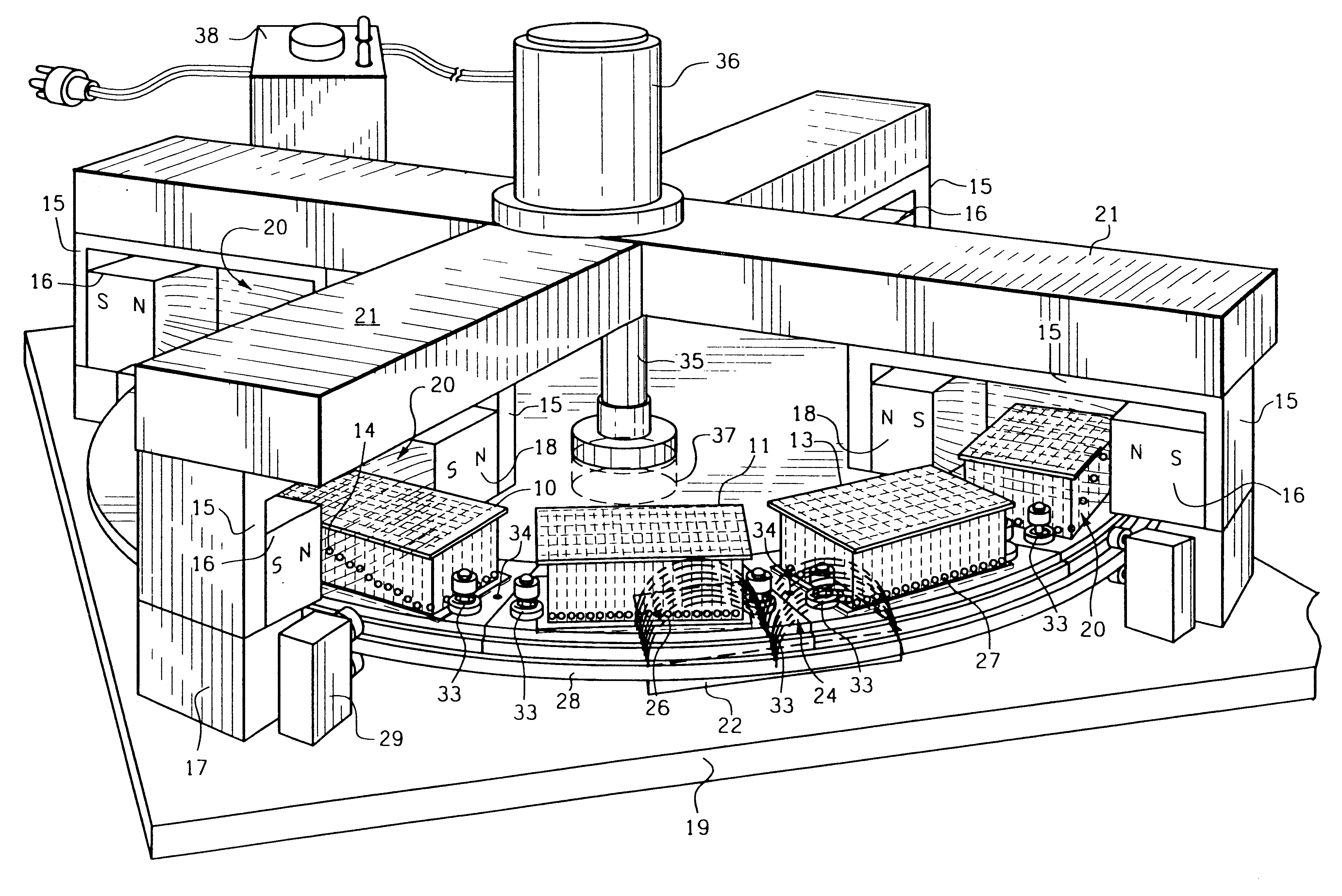
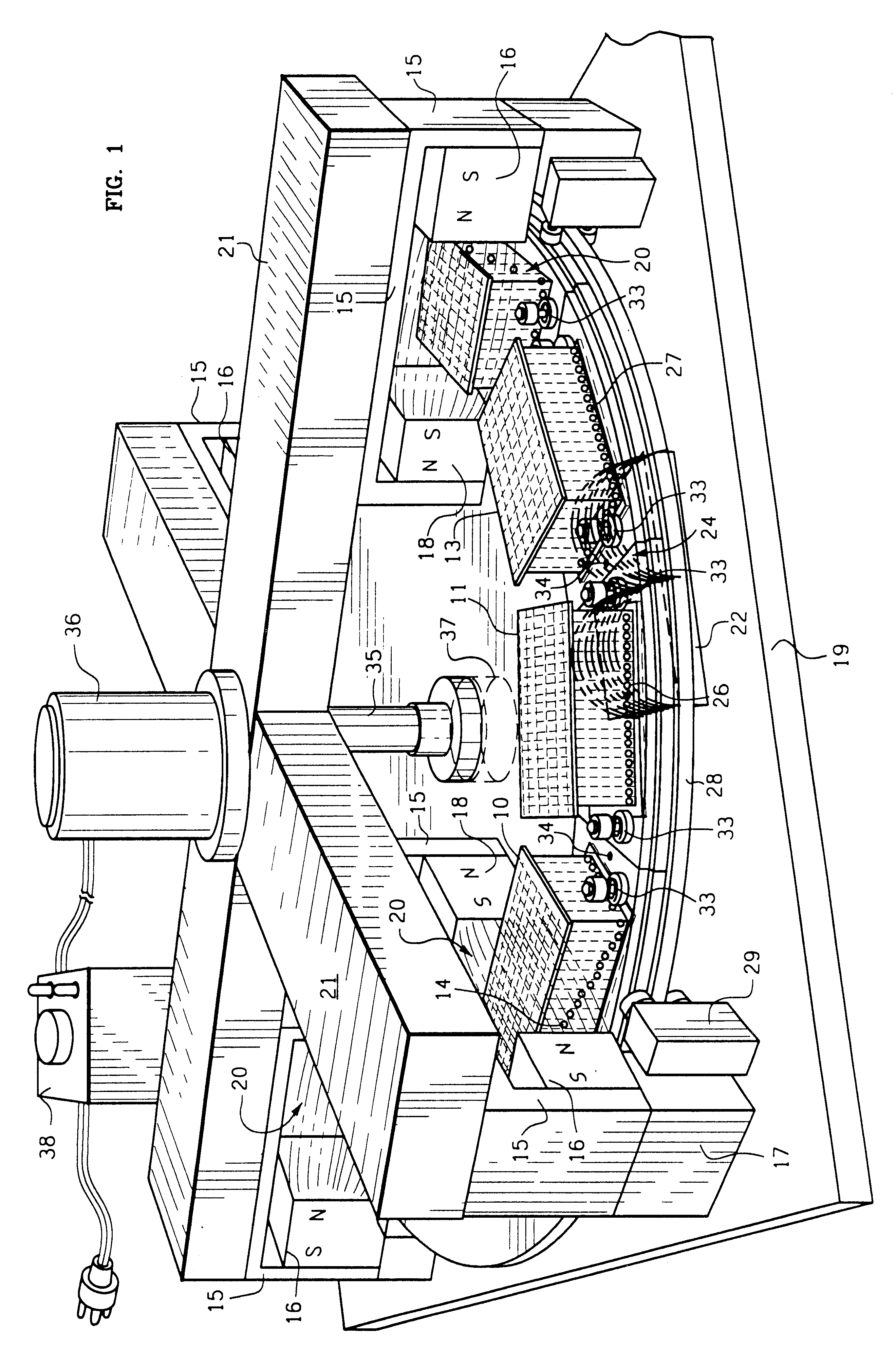
FIG. 1 illustrates how stir balls (14) are levitated as they enter the dipole focused levitation magnetic field (20) of the carousel levitation magnets (16 & 18) with their focusing dipole superstructure (15). As the deep well microplate (10) approaches the dipole focused magnetic levitation field (20) the stir balls (14) in the leading wells (12) are levitated. The closer to the dipole focused magnetic field (20) the greater the levitation. The stir balls (26) in the trailing deep well microplate (11) are pulled down to the bottom of the deep well microplate by the magnetic field (24) of a pull down magnet (22) located on the base plate (19) under the carousel wheel plate (28). The unaffected stir balls (27) in the third deep well microplate (13) are not influenced by either the dipole focused levitation magnetic field (20) or the pull down magnetic field (24) as they are between both magnetic fields. The steel dipole structure (15) is attached to the base plate (19) through an alu...


PUM

PropertyMeasurementUnit
magnetic fieldaaaaaaaaaa
magnetic fieldsaaaaaaaaaa
diametersaaaaaaaaaa

Abstract

The invention provides a simple method, devices and several machines for simultaneously stirring and aerating thousands of vessels or wells of microplates in a robust manner and with economy. This method uses the simple principle of magnetic stirrers being levitated vertically when passed laterally or vertically through a strong horizontal dipole magnetic field. The dipole magnetic fields may be produced by using permanent magnets, electromagnets or a modulating/reversing electro-magnetic field. Each vessel contains a magnetic ball, disc, bar, dowel or other shape (stirrers) which in their magnetic attraction to the dipole magnetic field will cause the stirrers to levitate up in the vessel as the stirrer's magnetic poles attempt to align with the center of the dipole's magnetic field. The stirrers will fall to the bottom of the vessel by gravity or by changing the relative position of the levitating magnetic field to pull them down, or by passing the vessel laterally over another magnetic field. The up and down movement of the stirrers provides a vigorous mixing of the contents of many vessels at same time. If the level of the vessel's meniscus is situated so the stirrers pass through it on their way up and down, the air/liquid interface is significantly increased thereby significantly increasing aeration of the liquid.

Description

BACKGROUND--FIELD OF INVENTIONThis invention provides a method, devices and machines to uniformly and simultaneously mix in tall vessels in such a manner as to increase the aeration of the liquid. The purpose is to provide a robust method, economical devices and very simple machines to uniformly stir and aerate the contents of one tall vessel or thousands of tall vessels, vials, test tubes or deep well microplate wells (6 well, 12 well, 24 well, 48 well, 96 well, 384 well, 864 well, 1536 well, 10,000 well, "U" bottom, "V" bottom, PCR and other deep well versions of those microplates) at the same time.BACKGROUND--Description of Prior ArtSuspending particulates in liquids, breaking up aggregates, aeration of gases in liquids, dissolving solids in liquids, emulsifying two liquids or mixing liquids together has usually been accomplished in large vessels, bottles, flasks and test tubes by magnetic horizontal spin stirring, orbital shakers, vortexing, rocking platforms, bubblers, vibrator...

Claims


Application Information

Patent Timeline
Patent Type & Authority Patents(United States)
IPC IPC(8): B01F13/00B01F13/08B01F15/00C40B60/14
CPCB01F13/0818C40B60/14B01J2219/00484B01J2219/00315B01F33/452
Inventor CLEVELAND, PATRICK H.MARKLE, JOHN R.
Owner V & P SCI
Why Eureka
Try Eureka