
Water return device

A technology of a water return device and a water return tank, which is applied in the field of molds, can solve the problems such as the inability to visually see the blockage of the water return pipe, the pressure and pressure of the return tank against the mold, and the impact on the surrounding environment.

Inactive Publication Date: 2016-11-23
KUNSHAN ZHONGYITE MACHINERY IND
View PDF6 Cites 1 Cited by
  • Summary
  • Abstract
  • Description
  • Claims
  • Application Information

AI Technical Summary

Problems solved by technology

[0002] The return water tank is usually used in the field of mold technology to cool the finished product to a certain temperature requirement. The existing return water tank generally does not have a pressure relief vent or a glass panel, and the vent of the return water tank The design is also relatively simple, and the existing return water tank has the following disadvantages: the pressure of the return water tank is too high, which may easily cause the air pressure back pressure to the mold cooling terminal; the user cannot intuitively see the return water status of each return water pipe and whether it is blocked; Water vapor is easy to spray directly outside and affect the surrounding environment

Method used


Image

  • Water return device
  • Water return device
  • Water return device

Examples


Embodiment Construction

[0025] The technical solutions of the present invention will be further described below in conjunction with the accompanying drawings and through specific implementation methods.

[0026] Preferred embodiment:

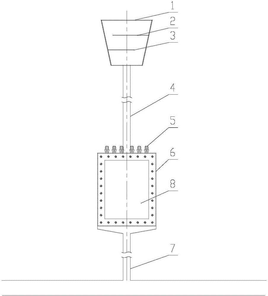
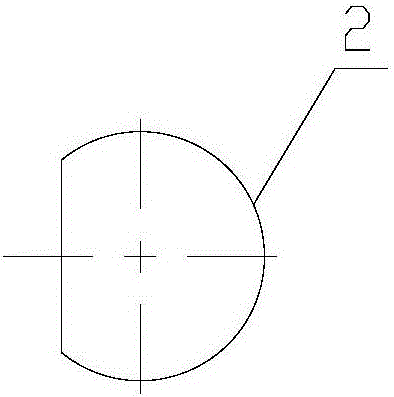
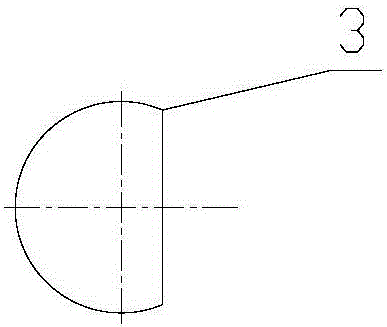
[0027] This preferred embodiment provides a water return device. like Figure 1 to Figure 5 As shown, the water return device includes a water return tank 6 and a funnel 1 . The top of the return tank 6 is connected to the bottom of the funnel 1 through the exhaust pipe 4 . The top of the return water tank 6 is connected with a plurality of return pipe connectors 5, preferably 12 evenly distributed return pipe connectors 5, the return pipe connectors 5 are used to connect various return pipes, and the bottom of the return tank 6 A drain pipe 7 is connected, and the drain pipe 7 is connected with a water return main pipe.

[0028] The top of the return tank 6 is also provided with a plurality of pressure relief vents, the specific number can be set according to actu...


PUM

PropertyMeasurementUnit
thicknessaaaaaaaaaa
lengthaaaaaaaaaa
widthaaaaaaaaaa

Abstract

The invention discloses a water return device, belongs to the technical field of dies and aims at solving the problem that existing water return boxes are prone to causing air pressure which counter-presses a die cooling terminal and inconvenient to observe. The water return device comprises a water return box and a funnel, the water return box is communicated with the funnel through an exhaust pipe, multiple pressure-release exhaust holes are formed in the top of the water return box and used for preventing the water return box with over-high pressure from causing air pressure which counter-presses the die cooling terminal, and an observation window is arranged on the water return box. The water return device can prevent the water return box with over-high pressure from causing the air pressure which counter-presses the die cooling terminal, and water return condition of each water return pipe and whether blockage occurs or not can be observed visually.

Description

technical field [0001] The invention relates to the technical field of molds, in particular to a water return device. Background technique [0002] The return water tank is usually used in the field of mold technology to cool the finished product to a certain temperature requirement. The existing return water tank generally does not have a pressure relief vent or a glass panel, and the vent of the return water tank The design is also relatively simple, and the existing return water tank has the following disadvantages: the pressure of the return water tank is too high, which may easily cause the air pressure back pressure to the mold cooling terminal; the user cannot intuitively see the return water status of each return water pipe and whether it is blocked; Water vapor is easy to spray directly outside and affect the surrounding environment. Therefore, the present invention urgently needs to provide a novel return water device so as to be better used in the technical field...

Claims


Application Information

Patent Timeline
Patent Type & Authority Applications(China)
IPC IPC(8): B22D30/00B29C35/16
CPCB22D30/00B29C35/16B29C2035/1616
Inventor 叶成高翔张传勇
Owner KUNSHAN ZHONGYITE MACHINERY IND
Learn More