A decanting device for a constant water level sequential batch process system

A process system and batch-sequencing technology, applied in the field of decanting, can solve problems such as mud run-off and drainage quality exceeding the standard, and achieve the effect of avoiding mud run-off and improving drainage quality

Active Publication Date: 2019-03-15
哈尔滨北方环保工程有限公司
View PDF2 Cites 0 Cited by
  • Summary
  • Abstract
  • Description
  • Claims
  • Application Information

AI Technical Summary

Problems solved by technology

[0010] The invention aims to solve the problem that the existing disc-shaped decanter has the phenomenon of mud run-off, which causes the drainage quality to exceed the standard.

Method used


Image

  • A decanting device for a constant water level sequential batch process system
  • A decanting device for a constant water level sequential batch process system
  • A decanting device for a constant water level sequential batch process system

Examples


specific Embodiment approach 2

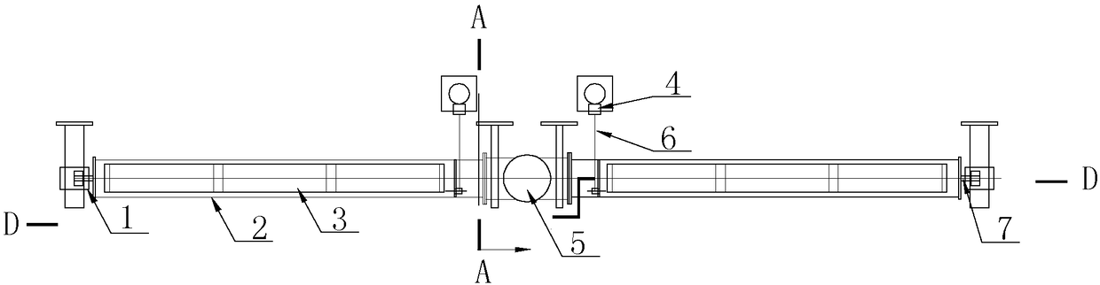
[0025] Specific embodiment 2. This embodiment is a further description of the decanting device of a constant water level sequence batch process system described in specific embodiment 1. The two horizontal ports and the lower side ports of the four-way pipe 5 are equipped with Lan, the two water-collecting horizontal pipes 2 are connected to the four-way pipe 5 through sealed packing, and the two water-collecting horizontal pipes 2 are rotatable in the four-way pipe 5, and the water-collecting vertical pipes 8 are connected to the four-way pipe through flanges. 5 connections.

specific Embodiment approach 3

[0026] Specific embodiment 3. This embodiment is a further description of the decanting device of a constant water level sequence batch process system described in specific embodiment 1 or 2. The closed ends of the two water-collecting horizontal pipes 2 are connected with support shafts , the support shaft is connected with the pool wall bearing of the sewage pool; and the support shaft is concentrically connected with the water collecting horizontal pipe 2 .

[0027] The screw drives the water-collecting horizontal pipe to rotate, and drives the supporting shaft to rotate, and the supporting shaft plays a role of supporting and fixing the water-collecting horizontal pipe, reducing the force on the water-collecting vertical pipe.

specific Embodiment approach 4

[0028] Embodiment 4. This embodiment is a further description of the decanting device of a constant water level sequence batch process system described in Embodiment 1. There are three rectangular collectors on the pipe wall of each water collecting horizontal pipe 2. The edge of each water collection port is welded with a metal plate perpendicular to the pipe wall, and the metal plate forms a water collection tank 3 along the water collection port.


PUM


Abstract

The invention discloses a constant water level repeated batch process system water decanting device, and relates to a water decanting method for a constant water level repeated batch process system. The device solves the problem that drainage quality exceeds standards due to sludge escape of an existing disk-shaped water decanter. Two shaft supports are fixed onto the wall of a water tank through fixing parts, one end of each of two transmission shafts is fixed onto the corresponding one of two water collection horizontal pipes, the other ends of the two transmission shafts are connected with the two shaft support through bearings, one end of each of the two water collection horizontal pipes is connected with the corresponding one of two horizontal ports of a four-way pipe, the other ends of the two water collection horizontal pipes are closed, a blind plate is arranged at an upper port of the four-way pipe and closely connected with the upper port of the four-way pipe, the upper end of a vertical water collection pipe is connected with a lower port of the four-way pipe, one end of a lead screw is connected with an electric push rod actuator, the other end of the lead screw is connected with the water collection horizontal pipes through connecting rods, water collection ports are formed in both the two water collection horizontal pipes, and water collection grooves are formed in the water collection ports. The device is applicable to water decanting of a sewage tank.

Description

technical field [0001] The invention relates to a water decanting method used in a constant water level sequence batch process system. Background technique [0002] CWSBR (Constant Waterlevel Sequencing Batch Reactors) is the constant water level sequencing batch process, which is developed on the basis of the SBR process. The SBR process is modified by using the constant water level operation mode and decanting equipment, and the flexible water level that can move back and forth The sail divides the reaction hold into three parts of variable volume, and decants the water using a constant water level decanter. Change the operation of variable water level, intermittent water intake, and intermittent water discharge in the conventional SBR process to CWSBR single tank constant water level, continuous water intake, and continuous water discharge. [0003] A working cycle of the constant water level sequence batch process includes different stages, including water intake, react...

Claims


Application Information

Patent Timeline
Patent Type & Authority Patents(China)
IPC IPC(8): C02F3/12B01D21/24
CPCB01D21/245C02F3/1263C02F2209/42C02F2303/14Y02W10/10
Inventor 杨少厚战树峰
Owner 哈尔滨北方环保工程有限公司
Why Eureka
Try Eureka