Special embroidery box for embroidered cloth

An embroidery frame and piece of cloth technology, applied in the field of embroidery machines, can solve problems such as inability to embroider, and achieve the effect of simple embroidery process and simple structure

Inactive Publication Date: 2016-11-23
上工富怡智能制造(天津)有限公司
View PDF11 Cites 6 Cited by
  • Summary
  • Abstract
  • Description
  • Claims
  • Application Information

AI Technical Summary

Problems solved by technology

When embroidering a piece of cloth, because the length of the piece of cloth is as long as tens of meters, the piece of cloth cannot be directly embroidered on the embroidery frame of the existing computerized embroidery machine

Method used


Image

  • Special embroidery box for embroidered cloth
  • Special embroidery box for embroidered cloth
  • Special embroidery box for embroidered cloth

Examples


Embodiment Construction

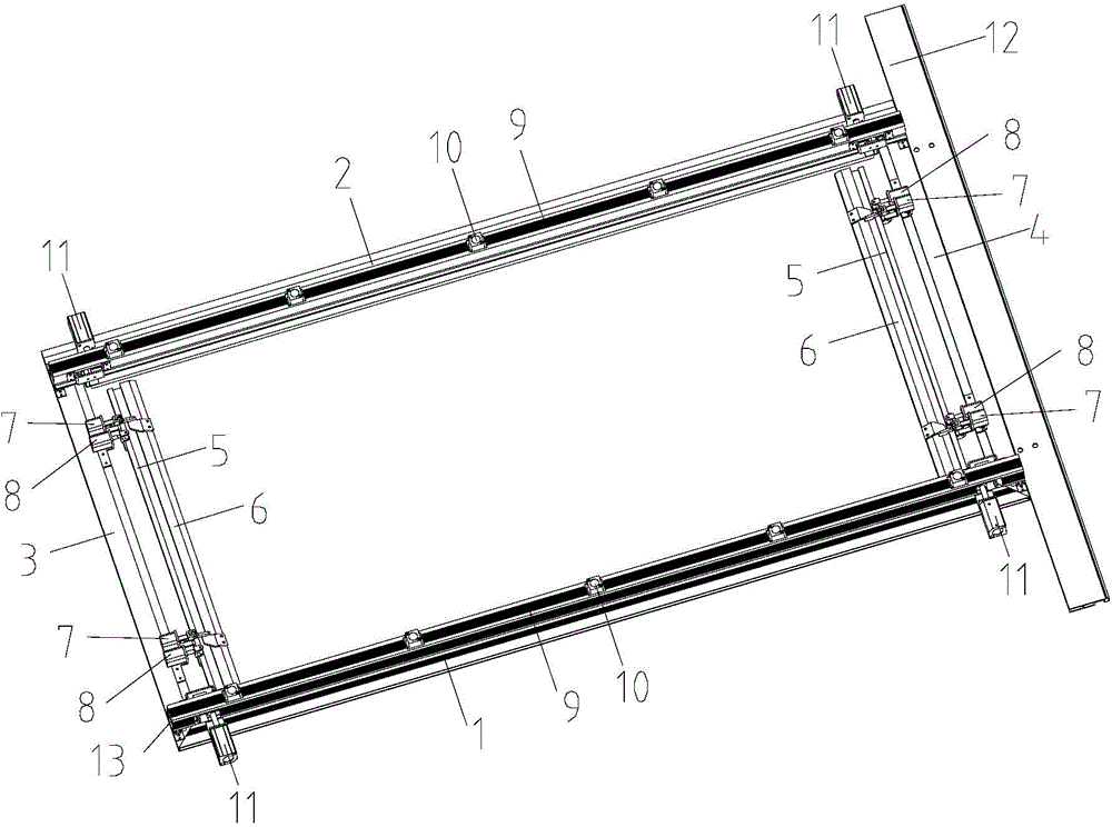
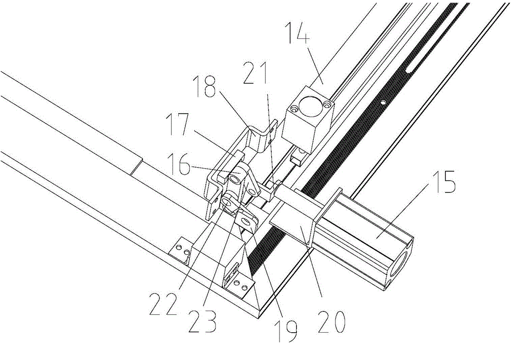
[0015] The following will be further described in conjunction with the accompanying drawings and specific implementation methods: A special embroidery frame for cloth embroidery, including: a front beam 1, a rear beam 2, a left beam 3, and a right beam 4 constituting the embroidery frame frame; Support beam 9 on 2, five pneumatic devices c10, two cylinder linkages 11; pneumatic devices a7, pneumatic device b8, rear side bars 5, left and right beam cover plates 6 installed on left beam 3 and right beam 4; The cylinder a15 of the cylinder linkage mechanism 11 is fixed on the front beam 1 through the angle plate 20, the cylinder joint 21 is located at the threaded end of the piston rod of the cylinder a15, and the cylinder linkage mechanism 11 is installed on the On the front beam 1; and the two-eye connecting rod 22 is located on the left side of the three-eye connecting rod 16 and connected with the middle hole of the three-eye connecting rod 16 with a pin shaft; and one end of ...


PUM


Abstract

The invention discloses a special embroidery box for embroidered cloth. The special embroidery box comprises a front beam, a rear beam, a left beam, a right beam, a supporting beam, five pneumatic devices c, two cylinder connecting rod mechanisms, a pneumatic device a, a pneumatic device b, a rear edge strip and left and right beam cover plates, wherein the front beam, the rear beam, the left beam and the right beam form an embroidery box frame; the supporting beam, the five pneumatic devices c and the two cylinder connecting rod mechanisms are mounted on the front beam and the rear beam; the pneumatic device a, the pneumatic device b, the rear edge strip and the left and right beam cover plates are mounted on the left beam and the right beam; a cylinder a of each of the cylinder connecting rod mechanisms is fixed on the front beam through an angle plate, and a cylinder joint is positioned at the threaded end of a piston rod of the cylinder a; each of the two cylinder connecting rod mechanisms and a fixing plate are mounted on the front beam through a two-eye connecting rod; the two-eye connecting rod is positioned on the left side of a three-eye connecting rod and is connected with a middle hole of the three-eye connecting rod through a pin shaft; one end of the cylinder joint is connected to the threaded end of the piston rod of the cylinder a, and the other end of the cylinder joint is connected with an upper end hole of the two-eye connecting rod through a pin shaft and is positioned on the right side of the three-eye connecting rod; the pneumatic devices are adopted for pressurization; the structure is simple; the automatic clamping and tensioning of the cloth in the embroidery process can be realized, so that the embroidery process becomes very simple and quick.

Description

technical field [0001] The invention relates to the technical field of embroidery machines in the textile industry, in particular to a special embroidery frame for cloth embroidery. Background technique [0002] The embroidery frame of the existing computer embroidery machine is composed of the front beam, the rear beam, the left beam, the fixed beam, and the right beam. , and the embroidery frame can only be embroidered on a single piece of fabric. [0003] Pieces of cloth are made by winding the cloth on a coiled plate or roll, the cloth surface is flat and tight, the sides are neat and wrinkle-free. When the piece of cloth is embroidered, because the length of the piece of cloth reaches tens of meters, the piece of cloth cannot directly be embroidered on the embroidery frame of the existing computerized embroidery machine. Contents of the invention [0004] The problem to be solved by the present invention is to provide a special embroidery frame for cloth embroidery,...

Claims


Application Information

Patent Timeline
Patent Type & Authority Applications(China)
IPC IPC(8): D05C9/04D05C9/12
Inventor 吴海忠张宝莉
Owner 上工富怡智能制造(天津)有限公司
Why Eureka
Try Eureka