
Coal-mine underground base plate anchor rod hole-drilling stabilizer

A base plate and anchor rod technology, applied in the direction of supporting devices, installation of anchor rods, drilling equipment and methods, etc., can solve the problems of large consumption of manpower and material resources, incompatibility, low efficiency, etc., and achieve the effect of simple structure

Inactive Publication Date: 2016-11-23
XUZHOU NAILI MACROMOLECULE TECH CO LTD
View PDF0 Cites 0 Cited by
  • Summary
  • Abstract
  • Description
  • Claims
  • Application Information

AI Technical Summary

Problems solved by technology

[0004] Improve the strength of the surrounding rock of the floor, mainly including floor grouting, floor bolt support, etc. When using bolt support for the floor, it is necessary to drill the floor first. The traditional method needs to be above the drill pipe during the drilling process. Wooden columns or reverse air legs are used to support the roof of the roadway to provide reverse support. However, in order to ensure that the bottom plate of the roadway will not be damaged before the anchor is installed, the anchor must be installed within a certain distance from the excavation face. The size of this distance is related to the nature of the floor rock, and generally should not be greater than 10 meters. At the same time, in order to ensure that the roadway excavation speed is not affected, the bolt installation speed is usually fast, and this traditional drilling method is not only complicated and labor-intensive. The consumption of material resources is large, and the speed of drilling and installing bolts is slow and the efficiency is low, which is not suitable for the requirements of rapid roadway formation

Method used


Image

  • Coal-mine underground base plate anchor rod hole-drilling stabilizer
  • Coal-mine underground base plate anchor rod hole-drilling stabilizer

Examples


Embodiment Construction

[0018] The present invention will be further described below in conjunction with the accompanying drawings.

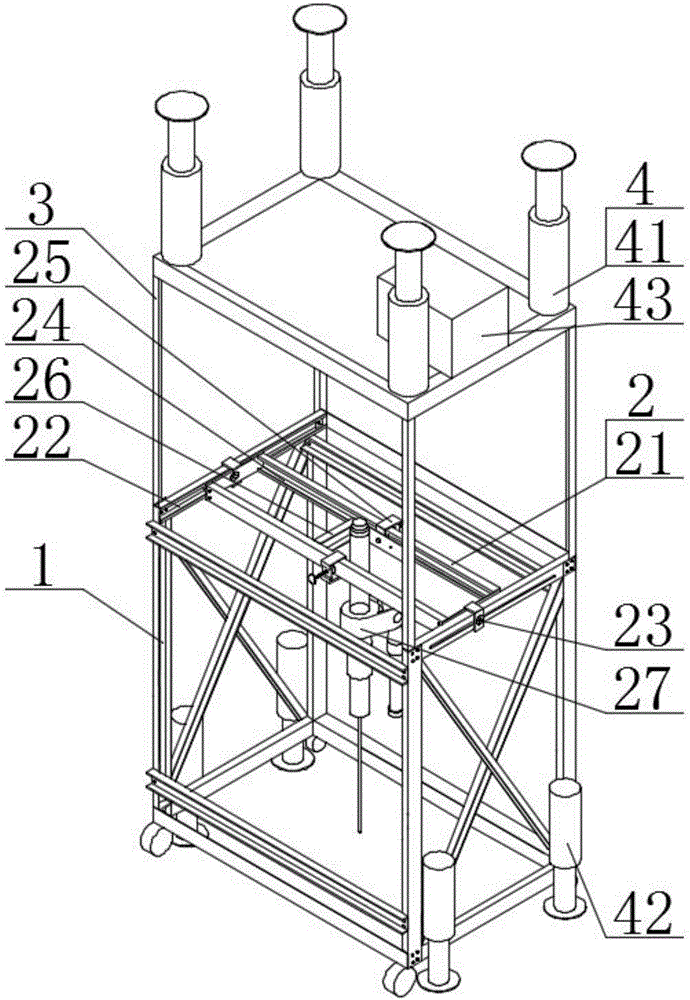
[0019] Such as figure 1 As shown, the bottom plate bolt drilling stabilizing device of the coal mine comprises an underframe 1, a working part 2, an upper frame 3 and a device positioning part 4.

[0020] The upper frame 3 is fixedly installed on the underframe 1, and the bottom end of the underframe 1 is provided with rollers.

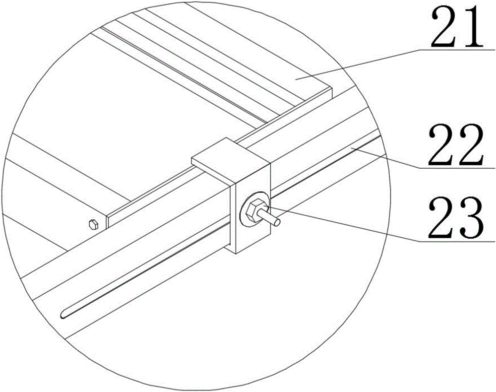
[0021] The working part 2 is installed on the chassis 1, including a body 21, front and rear guide slots 22, front and rear positioning locking nuts 23, left and right guiding slots 24, left and right positioning locking nuts 25, drilling rig mounting frame 26 and drilling rig 27 The main body 21 is a rectangular frame structure, and its left and right end faces are erected on the front and rear guide slots 22 arranged on the inner side of the chassis 1 in the front and rear direction through the cylindrical sliding shoes positioned at the ce...


PUM


Abstract

The invention discloses a stable drilling device for anchor rod drilling on the bottom plate of a coal mine, which comprises a bottom frame (1), a working part (2), an upper frame (3) and a device positioning part (4); The working parts are installed on the chassis, including the main body (21), the front and rear guide slots (22), the front and rear positioning lock nuts (23), the left and right guide slots (24), the left and right positioning lock nuts (25), the drilling rig installation frame (26) and drilling rig (27); the device positioning components include top positioning support hydraulic cylinder (41), bottom positioning support hydraulic cylinder (42) and control valve group (43), and the control valve group is respectively connected with top positioning support hydraulic cylinder and Bottom positioning support hydraulic cylinder connection. The structure of the anchor drilling stabilizing device in the underground floor of the coal mine is simple, and it can realize the rapid drilling operation on the roadway floor during the drilling process, thereby improving the installation speed of the bolt as a whole, and adapting to the requirements of rapid roadway formation.

Description

technical field [0001] The invention relates to a drilling device, in particular to a coal mine underground bottom plate anchor drilling stabilizing device suitable for drilling and bolt support for roadway bottom plates in coal mines, and belongs to the technical field of underground support equipment. Background technique [0002] Due to the different characteristics of the rock mass at different depths around the roadway and the different stress environments, the surrounding rock is prone to uncoordinated deformation due to factors such as geological periodic movement and groundwater pressure, especially for underground mining in coal mines. The surrounding rock will deform and move into the roadway. The phenomenon that the floor of the roadway or the gob floor rises upwards is called the floor heave. The floor heave is a dynamic phenomenon that often occurs in the mine roadway. It is related to the nature of the surrounding rock. , impact of mining, mining depth and geol...

Claims


Application Information

Patent Timeline
Patent Type & Authority Applications(China)
IPC IPC(8): E21B7/02E21B7/04E21B15/04E21D20/00
CPCE21B7/024E21B7/04E21B15/003E21B15/04E21B15/045E21D20/003
Inventor 耿志国
Owner XUZHOU NAILI MACROMOLECULE TECH CO LTD
Learn More