Method and system for operating a cam-driven pump

A technology for driving pumps and cams, applied in the components of pumping devices for elastic fluids, charging systems, pumps, etc., can solve problems such as damage to plunger cams

Inactive Publication Date: 2016-11-23
GM GLOBAL TECH OPERATIONS LLC
View PDF4 Cites 2 Cited by
  • Summary
  • Abstract
  • Description
  • Claims
  • Application Information

AI Technical Summary

Problems solved by technology

The disadvantage is damage

Method used


Image

  • Method and system for operating a cam-driven pump

Examples


Embodiment Construction

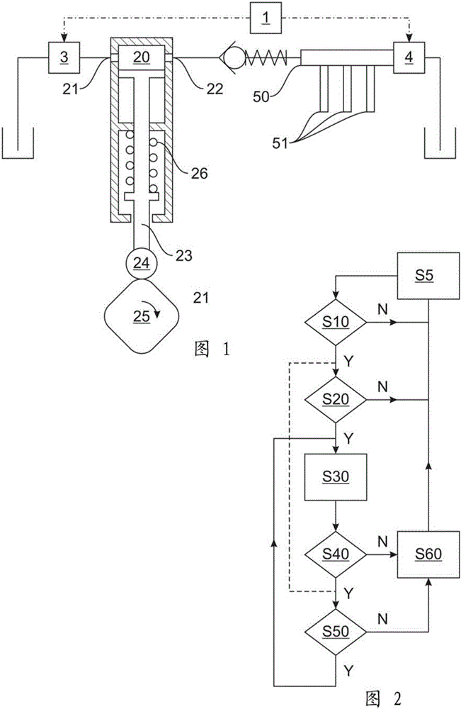
[0044] figure 1 A part of an internal combustion engine arrangement according to an embodiment of the invention is shown having an internal combustion engine comprising an injector 51 and a pump arrangement comprising a control system in the form of an ECU 1 .

[0045] The pump device comprises a cam-driven high-pressure fuel pump of a common rail system, comprising a working chamber 20 with an inlet 21 and an outlet 22, and an actuating means with a plunger 23 and a cam follower 24, said cam follower Driven by a cam 25 which is itself driven by a camshaft (not shown) of the internal combustion engine. The actuating means 23 , 24 are permanently biased towards the cam 25 by biasing means in the form of a spring 26 .

[0046] The pump device further comprises a valve device comprising an inlet valve in the form of DIV3 in fluid communication with the inlet 21 and a discharge valve in the form of PRV4 of the common rail system in fluid communication with the outlet 22 via a com...


PUM


Abstract

A method for automatically operating a cam-driven pump is disclosed. The pump is monitored to determine (S10, S20, S40, S50) whether a specified detachment condition or potential detachment of an actuator (23, 24) of the pump from a driving cam (25) is occurring. The pump is operated (S30) in a minimal pressure holding mode to provide a minimal pressure within a working chamber (20) of the pump so as to bias the actuator (23, 24) towards the cam (25) if it is determined that the detachment condition is occurring.

Description

technical field [0001] The invention relates to a method and operation for automatically operating a cam-driven pump, a pump device comprising said operating system, an internal combustion engine device comprising said pump device, a vehicle comprising said internal combustion engine device and a device for carrying out the method Computer Program Products. Background technique [0002] According to internal convention, pumps are known which comprise a plunger driven by a rotating cam. Such a pump may in particular supply an internal combustion engine, in particular a so-called common rail. [0003] In particular, when such an internal combustion engine is stopped, for example in a cruise mode of the vehicle, such a plunger may temporarily disengage from the drive cam due to its inertia. The downside is damage to the plunger and / or cam. Contents of the invention [0004] It is therefore an object of the present invention to improve the performance, especially the durabi...

Claims


Application Information

Patent Timeline
IPC IPC(8): F02M59/10F02D41/38F02M59/46
CPCF02D41/3809F02M59/102F02M59/46F02D41/042F02D41/3845F04B9/042F04B49/03F04B53/14F02D2041/224F02D2200/101F02D41/3005F04B49/22F02M63/0265F04B53/147F02D1/10F04B19/22F04B17/05F04B49/065
Inventor M.梅利斯F.C.佩谢S.尼杜A.莫拉
Owner GM GLOBAL TECH OPERATIONS LLC
Why Eureka
Try Eureka