Automatic retaining device for vehicle on ramp

A technology of stop device and ramp, applied in the direction of transmission control, components with teeth, belt/chain/gear, etc., can solve the problem of high manufacturing matching price, and achieve the effect of reducing wear and tear

Active Publication Date: 2016-11-23
蒋保太
View PDF8 Cites 0 Cited by
  • Summary
  • Abstract
  • Description
  • Claims
  • Application Information

AI Technical Summary

Problems solved by technology

In addition, due to the high price of the manufacturing equipment of this technology, it is determined that it can only be limited to the assembly of high-end cars, so that the low-end car groups unconditionally choose

Method used


Image

  • Automatic retaining device for vehicle on ramp
  • Automatic retaining device for vehicle on ramp

Examples


Embodiment Construction

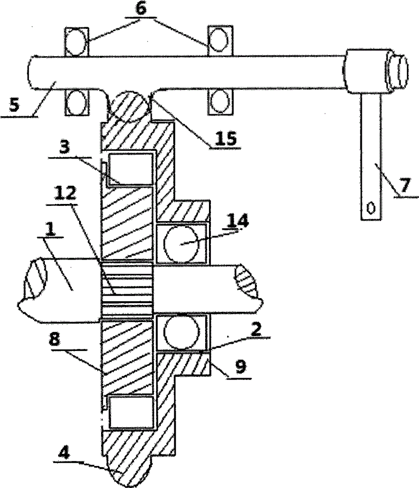
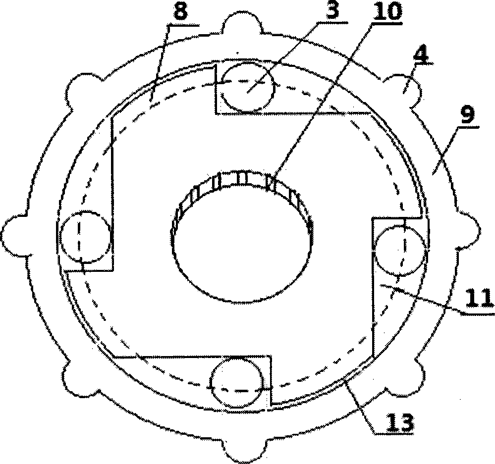
[0016] The present invention is a single structure device, as a device for preventing the vehicle from retreating, it can be installed at a certain position between the power output shaft inside and outside the gearbox to the power input shaft of the rear axle in the transmission system (electric vehicles can also be installed to one shaft of the gearbox).

[0017] Such as figure 1 figure 2 Shown, the present invention comprises power shaft 1, backstop driving disk 8, backtracking driven disk 9 and backstop joystick 5, and power shaft 1 is installed on the axle center of backstop driving disk 8 and backstop driven disk 9. A basin-shaped driven disc cavity 13 is set in the main body of the anti-retreat driven disc 9 , and the center portion of the end of the anti-retreat driven disc 9 is narrowed into a bearing hole 2 . The backstop driving disc 8 is assembled in the cavity 13 of the driven disc. The back-stop driving disk 8 is in the shape of a wind wheel, and each wind wh...


PUM


Abstract

The invention provides an automatic retaining device for a ramp. The automatic retaining device is mounted between a power output shaft and a rear axle power input shaft, and the power output shaft and the rear axle power input shaft are located inside and outside a gearbox of a transmission system. The automatic retaining device comprises a power shaft, a driving retaining disc, a driven retaining disc and a retaining operation rod, wherein the power shaft is mounted at the axis of the driving retaining disc and the axis of the driven retaining disc. A basin-shaped driven disc cavity is formed in a driven retaining disc body, and the driving retaining disc is assembled in the driven disc cavity. The driving retaining disc is in the shape of a wind wheel, each wind wheel notch in the periphery of the driving retaining disc forms a roller chamber, and a roller is arranged in each roller chamber, so that the driving retaining disc and the driven retaining disc body are matched together through the rollers. The automatic retaining device is free of a brake, simple in structure, small in size, low in weight, high in scientific and technological content, low in manufacturing cost, reliable in performance and easy and convenient to operate.

Description

technical field [0001] The invention belongs to a braking system of a vehicle, in particular to an automatic back-stopping device for slopes. Background technique [0002] At present, the existing vehicle automatic parking technology still uses the vehicle's own brake as the basis for braking and parking, and completes the vehicle's automatic parking by adding electronically controlled electric technology. This automatic parking method determines that the vehicle will be parked when it is parked. Regardless of whether it is necessary to park, any parking must go through a process cycle from parking to unparking. Although the use of this parking technology has brought great convenience to the driver, especially the uphill start of the vehicle, too frequent use of the brake for parking will undoubtedly greatly reduce the conventional service life of the vehicle brake. In addition, because of the high price of the manufacturing package of this technology, it is determined that...

Claims


Application Information

Patent Timeline
Patent Type & Authority Applications(China)
IPC IPC(8): F16H63/34
Inventor 蒋保太蒋春岳蒋岳林
Owner 蒋保太
Why Eureka
Try Eureka