Landscaping lamp

A landscaping and lamp holder technology, applied in lighting and heating equipment, lighting devices, fixed lighting devices, etc., can solve problems such as unfavorable control, high cost, low power, etc., and achieve the effect of reducing space occupation and prolonging service life.

Inactive Publication Date: 2016-11-23
张日龙
View PDF5 Cites 0 Cited by
  • Summary
  • Abstract
  • Description
  • Claims
  • Application Information

AI Technical Summary

Problems solved by technology

But the landscaping lights used in plant planting usually only have the function of simply accelerating the growth of plants. The light brightness of the lighting is small, the projection range is short, and the power is low, so it is not suitable for use in some gardens where trees are densely planted.
[0003] In addition, landscaping lights are a kind of landscape lights that are widely used in parks, green belts in residential areas, etc. At present, landscaping lights are mainly made of steel frames, glass, and plastic materials, which are high in cost and complicated in production technology. It is impossible to break through the tradition, and the materials are easy to age. In addition, due to the low power of the existing garden lights, there are many green lights arranged in the garden, which has a certain impact on the vegetation environment of the garden and takes up a lot of energy. garden space
Moreover, when some existing landscaping lamps are in use, due to the long time and high temperature, the lamp holders are cracked, and the garden lamps are damaged, and the existing lamp holders are not waterproof, insulated and flame-retardant. Obvious effect, high temperature is easy to break or melt, and then cause open circuit and fire. Therefore, in summary, it is necessary to design a kind of landscaping lamp that can solve the problem of single function, unfavorable control and large land occupation. It also needs to design A hinged lamp holder that can be insulated, flame-retardant, wear-resistant and waterproof

Method used


Image

  • Landscaping lamp
  • Landscaping lamp
  • Landscaping lamp

Examples


Embodiment 1

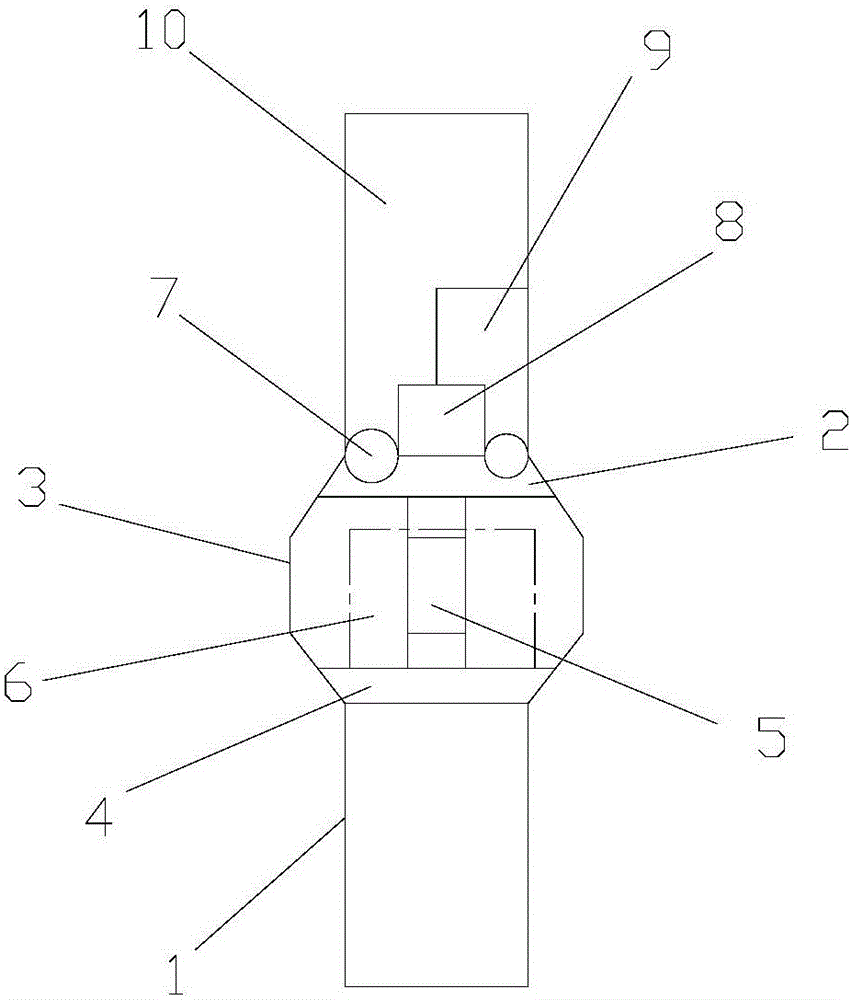
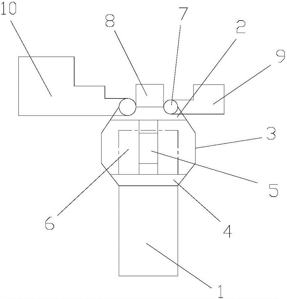
[0024] refer to Figure 1-2 As shown, a landscaping lamp includes a base 1 and a hinged lamp holder 2, the upper end of the base 1 is provided with a lighting lamp 3, the lower end of the lighting lamp 3 is provided with a fixed lamp holder 4, and the fixed lamp The seat 4 is fixed with the base 1, and the side of the lighting lamp 3 is provided with a frame 5, and the frame 5 is fixed with the fixed lamp holder 4, and the LED lamp body 6 is arranged inside the lighting lamp 3, and the hinged The lamp holder 2 is located above the lighting lamp 3, and the hinged lamp holder 2 is fixed to the frame 5. The hinged lamp holder 2 is provided with a hinged seat 7, a small projection lamp 9 and a large projection lamp 10. The hinged seat 7 Located at both ends of the hinged lamp base 2 , a fixed block 8 is arranged between the hinged bases 7 , and the small projection lamp 9 and the large projection lamp 10 are hinged to the hinged base 7 .

[0025] The hinged lamp holder 2 is made ...

Embodiment 2

[0039] refer to Figure 1-2 As shown, a landscaping lamp includes a base 1 and a hinged lamp holder 2, the upper end of the base 1 is provided with a lighting lamp 3, and the lower end of the lighting lamp 3 is provided with a fixed lamp holder 4, and the fixed lamp The seat 4 is fixed with the base 1, and the side of the lighting lamp 3 is provided with a frame 5, and the frame 5 is fixed with the fixed lamp holder 4, and the LED lamp body 6 is arranged inside the lighting lamp 3, and the hinged The lamp holder 2 is located above the lighting lamp 3, and the hinged lamp holder 2 is fixed to the frame 5. The hinged lamp holder 2 is provided with a hinged seat 7, a small projection lamp 9 and a large projection lamp 10. The hinged seat 7 Located at both ends of the hinged lamp base 2 , a fixed block 8 is arranged between the hinged bases 7 , and the small projection lamp 9 and the large projection lamp 10 are hinged to the hinged base 7 .

[0040] The hinged lamp holder 2 is m...

Embodiment 3

[0054] refer to Figure 1-2 As shown, a landscaping lamp includes a base 1 and a hinged lamp holder 2, the upper end of the base 1 is provided with a lighting lamp 3, the lower end of the lighting lamp 3 is provided with a fixed lamp holder 4, and the fixed lamp The seat 4 is fixed with the base 1, and the side of the lighting lamp 3 is provided with a frame 5, and the frame 5 is fixed with the fixed lamp holder 4, and the LED lamp body 6 is arranged inside the lighting lamp 3, and the hinged The lamp holder 2 is located above the lighting lamp 3, and the hinged lamp holder 2 is fixed to the frame 5. The hinged lamp holder 2 is provided with a hinged seat 7, a small projection lamp 9 and a large projection lamp 10. The hinged seat 7 Located at both ends of the hinged lamp base 2 , a fixed block 8 is arranged between the hinged bases 7 , and the small projection lamp 9 and the large projection lamp 10 are hinged to the hinged base 7 .

[0055] The hinged lamp holder 2 is made ...


PUM


Abstract

The invention discloses a landscaping lamp. The landscaping lamp comprises a base and a hinge lamp holder. A lighting lamp is arranged at the upper end of the base, a fixing lamp holder is arranged at the lower end of the lighting lamp, and the fixing lamp holder and the base are fixed; a frame is arranged on the side of the lighting lamp, and the frame and the fixing lamp holder are fixed; an LED lamp body is arranged in the lighting lamp, the hinge lamp holder is located above the lighting lamp, and the hinge lamp holder and the frame are fixed; the hinge lamp holder is provided with hinge bases, a small projection lamp and a large projection lamp; the hinge bases are located at the two ends of the hinge lamp holder, and a fixing block is arranged between the hinge bases; and the small projection lamp and the large projection lamp are hinged to the hinge bases. The landscaping lamp has the beneficial effects of having two purposes including lighting and projection and being convenient to control and small in floor space; and the hinge lamp holder can achieve insulation and inflaming retarding and has good wear-resisting and waterproof effect.

Description

technical field [0001] The invention specifically relates to a garden greening lamp. Background technique [0002] With the continuous development of garden technology, the current plant planting technology is no longer limited to fertilization. By changing the light irradiation, the growth rate of plants can be accelerated, so there are landscaping lights. But the landscaping lights used in plant planting usually only have the function of simply accelerating the growth of plants. The light brightness of the lighting is small, the projection range is short, and the power is low, so it is not suitable for use in some gardens where trees are densely planted. [0003] In addition, landscaping lights are a kind of landscape lights that are widely used in parks, green belts in residential areas, etc. At present, landscaping lights are mainly made of steel frames, glass, and plastic materials, which are high in cost and complicated in production technology. It is impossible to br...

Claims


Application Information

Patent Timeline
Patent Type & Authority Applications(China)
IPC IPC(8): F21S8/00F21V17/10C08L63/00C08L9/02C08L67/02C08K13/04C08K3/26C08K3/22C08K7/14
CPCF21S8/00C08L63/00C08L2201/02C08L2203/20C08L2205/035F21V17/10C08L9/02C08L67/02C08K13/04C08K2003/265C08K2003/2241C08K7/14
Inventor 张日龙
Owner 张日龙
Why Eureka
Try Eureka