An optical system

A technology of optical system and light beam, which is applied in the field of optical system, can solve problems such as spending more time, wasting time, and not firmly pointing

Inactive Publication Date: 2016-11-23
SINTAI OPTICAL SHENZHEN CO LTD +1
View PDF9 Cites 5 Cited by
  • Summary
  • Abstract
  • Description
  • Claims
  • Application Information

AI Technical Summary

Problems solved by technology

[0003] In the above-mentioned structure, it is necessary to utilize the mirror seat of the mirror 20 to adjust the optical axis of the reflected light beam so that the light beam can enter the roof prism optical system 40, but this adjustment operation is not easy, it takes a lot of time, and because the reflected light is adjusted Afterwards, fixing the seat of the reflector 20 with glue is sometimes not firm, and it takes more time to process, which is a waste of time

Method used


Image

  • An optical system
  • An optical system

Examples


Embodiment Construction

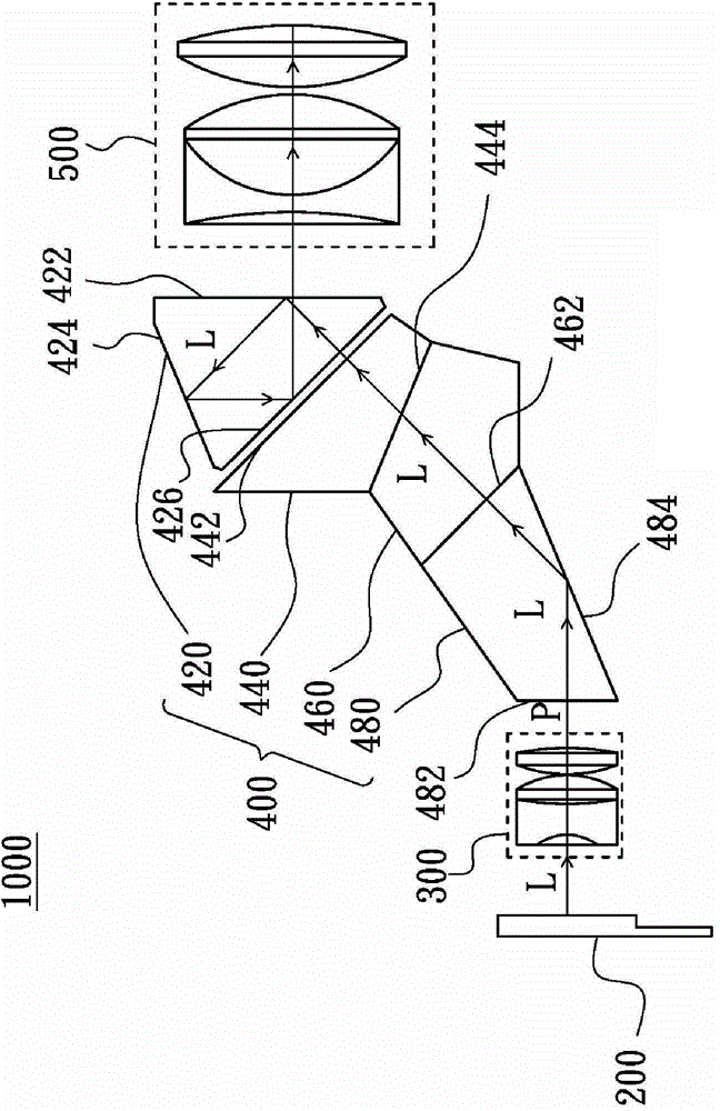
[0011] see figure 2 , which represents the optical system of the present invention. The optical system 1000 of the present invention includes a light source 200 , a focusing lens group 300 , a roof prism optical system 400 and a projection lens group 500 .

[0012] The roof prism optical system 400 includes a roof prism 420 , a first triangular prism 440 , a second triangular prism 460 and a third triangular prism 480 . The roof prism 420 has a first light exit / entry surface 422 , a roof surface 424 and a first reflective surface 426 . The first triangular prism 440 has a second reflective surface 442 and a film surface 444 , and the second reflective surface 442 is disposed adjacent to the first reflective surface 426 . The second triangular prism 460 is arranged adjacent to the film surface 444 of the first triangular prism 440 and has a second light exit / entry surface 462, and the third triangular prism 480 is adjacent to the second light exit / entry surface 462 of the se...


PUM


Abstract

The invention relates to an optical system comprising a roof prism, a first triangular prism, a second triangular prism, a third triangular prism and a light source. After a light beam emitted by a light source enters the third triangular prism via a third light inlet/outlet surface of the third triangular prism, the light beam is totally reflected by a third reflection plane of the third triangular prism and then enters the second triangular prism via a second light inlet/outlet surface of the second triangular prism; then the light beam sequentially goes through a thin film surface and a second reflecting surface of the first triangular prism to enter the roof prism; and afterwards, the light beams is sequentially and totally reflected by a first light inlet/outlet surface, a roof surface and a first totally reflecting surface, and then goes out from the first light inlet/outlet surface.

Description

technical field [0001] The present invention relates to an optical system, in particular to an optical system that uses a prism to guide light beams into a roof prism optical system. Background technique [0002] see figure 1 , which represents a known optical system. This known optical system 100 includes a light source 10 , a reflector 20 , a focusing lens group 30 , a roof prism optical system 40 and a projection lens group 50 . The roof prism optical system 40 includes a roof prism 42 , a first triangular prism 44 and a second triangular prism 46 . The light source 10 includes an organic light-emitting diode (Organic Light-emitting Diode, OLED). The light beam M emitted by the light source 10 passes through the focusing lens group 30 after being reflected by the reflector 20, and then enters the roof prism optical system 40, and the light beam M enters the roof prism optical system 40 Pass through the second triangular prism 46 and the first triangular prism 44 in sequ...

Claims


Application Information

Patent Timeline
Patent Type & Authority Applications(China)
IPC IPC(8): G02B17/08
Inventor 张敬民刘华唐
Owner SINTAI OPTICAL SHENZHEN CO LTD
Why Eureka
Try Eureka