
Motor rotor

A motor rotor and rotor shaft technology, applied in the field of electric motors, can solve the problems of reduced service life, unreliable heat dissipation, etc., and achieve the effect of improving service life

Inactive Publication Date: 2016-11-23
HUZHOU NANXUN XINLONG MOTOR
View PDF3 Cites 0 Cited by
  • Summary
  • Abstract
  • Description
  • Claims
  • Application Information

AI Technical Summary

Problems solved by technology

[0002] The motor is used to realize the conversion between electrical energy and mechanical energy and mechanical energy and electrical energy. The rotor of the motor is mainly composed of multiple rotor punches superimposed together. The installation through holes on the punching sheet are connected to each other, and the magnetic strips are fixed on the installation through holes. Since the motor rotor will generate heat during high-speed operation, the heat dissipation is unreliable and the service life is reduced.

Method used


Image

  • Motor rotor
  • Motor rotor
  • Motor rotor

Examples


Embodiment Construction

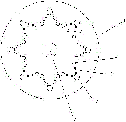
[0015] The present invention as Figure 1-3 As shown, it includes a rotor shaft and a number of rotor punches 1. The center of the rotor punch is provided with a shaft hole 2 for placing the rotor shaft. The rotor punch is evenly distributed on the circumference with a number of mounting holes 3 for placing magnetic strips. ;

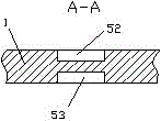
[0016] It also includes a number of heat dissipation groups, the heat dissipation groups are arranged on the rotor punch, and the heat dissipation groups correspond to the installation holes one by one. The heat dissipation groups include a pair of air holes 4, and the installation holes are located between the pair of air holes. The pair of air holes are respectively connected to the installation holes through the connecting channel 5, so that the installation hole and the pair of air holes form an open triangle (that is, one side of the triangle is open).

[0017] Such as figure 2 As shown, the first embodiment of the present invention is: the conn...


PUM


Abstract

The invention relates to a motor rotor. The motor rotor with simple structure and improved heat dissipation effect is provided. The motor rotor comprises a rotor shaft and a plurality of rotor sheets, wherein a shaft hole used for holding the rotor shaft is formed in the center of each rotor sheet, and a plurality of installation holes for holding magnet strips are uniformly formed in the circumference of each rotor sheet; the motor rotor also comprises a plurality of heat dissipation groups arranged on the rotor sheets, every heat dissipation set corresponds with one installation hole, each heat dissipation set comprises a pair of air holes, each installation hole is located between the corresponding pair of air holes, each pair of air holes are respectively connected with the corresponding installation hole via connection channels, and thus each installation hole and the corresponding pair of air holes form an open triangle. The motor rotor can effectively dissipate heat when in operation is effectively ensured, and the service life of the motor rotor is prolonged.

Description

technical field [0001] The present invention relates to electric motors, and more particularly to electric motor rotors. Background technique [0002] The motor is used to realize the conversion between electrical energy and mechanical energy and mechanical energy and electrical energy. The motor rotor is mainly composed of multiple rotor punches superimposed together, and the rotor shaft runs through the superimposed rotor punches, and the rotor punches are provided with installation through holes. After stacking, the rotor The installation through holes on the punching sheet are connected to each other, and a magnetic strip is fixed on the installation through holes. Because the motor rotor will generate heat during high-speed operation during operation, the heat dissipation is unreliable, and the service life is reduced. Contents of the invention [0003] Aiming at the above problems, the present invention provides a motor rotor with simple structure and improved heat d...

Claims


Application Information

Patent Timeline
Patent Type & Authority Applications(China)
IPC IPC(8): H02K1/22H02K1/32
CPCH02K1/22H02K1/32
Inventor 何梦琦谢静娟
Owner HUZHOU NANXUN XINLONG MOTOR
Learn More