Surface light source device

a light source and surface technology, applied in the direction of lighting and heating apparatus, instruments, mechanical equipment, etc., can solve the problems of reducing the lifetime and reliability of causing the temperature in the vicinity of the light emitting elements to rise, and reducing the light flux emitted from the point light source, so as to efficiently dissipate the heat generated

Active Publication Date: 2007-10-25
TRIVALE TECH LLC
View PDF3 Cites 87 Cited by
  • Summary
  • Abstract
  • Description
  • Claims
  • Application Information

AI Technical Summary

Benefits of technology

[0009]According to the present invention, a surface light-source device is obtained that can efficiently dissipate heat generated in point light sources thereof and enables the point light sources to be replaced.

Problems solved by technology

Either way, however, causes temperature in the vicinity of the light emitting elements to rise due to heat generation associated with light emission of the light emitting elements.
As a result, light flux emitted from the point light source is reduced, which raises a problem with reduction of point light-source's lifetime and reliability.
The surface light-source devices disclosed in the patents cited above, however, have a problem in that the peripheries or thicknesses thereof inevitably become large due to their structures or in that the number of parts increases.
Moreover, they also have another problem in that the surface light-source devices cannot be used in a liquid crystal display device for a machine tool or the like operated over a long period of time because their light sources cannot be replaced.

Method used


Image

  • Surface light source device
  • Surface light source device
  • Surface light source device

Examples


embodiment 1

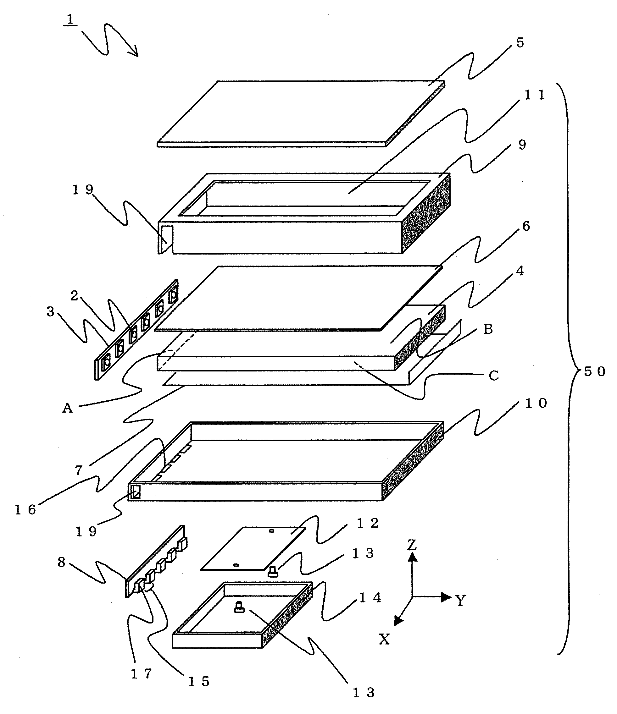
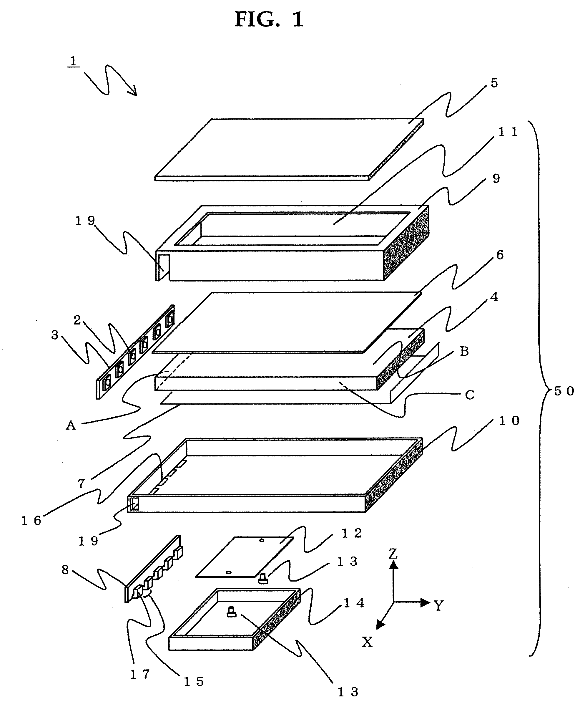
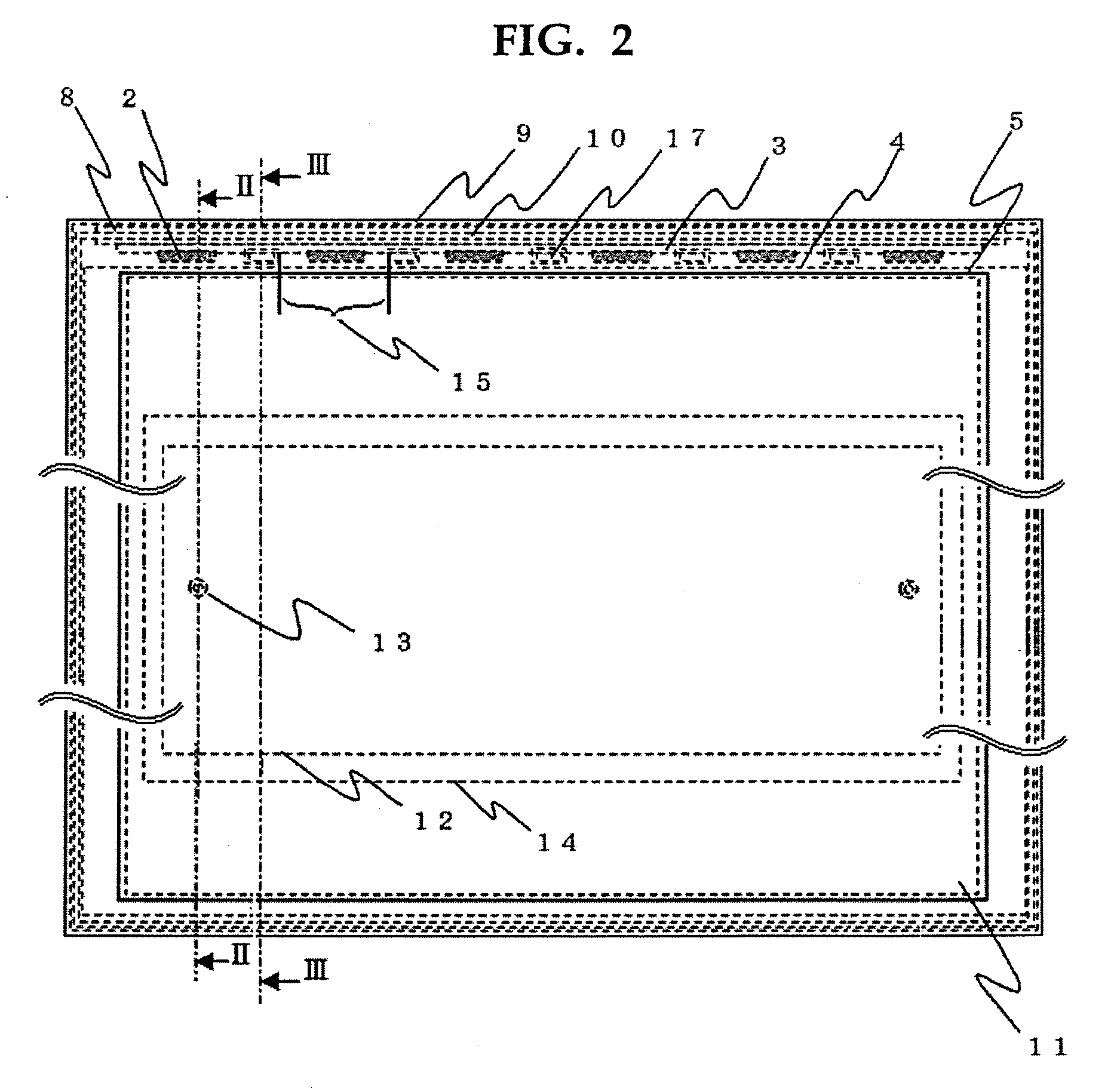
[0025]Embodiment 1 of the present invention is explained with reference to FIGS. 1 through 5. Here, FIG. 1 is an exploded perspective view for explaining a configuration of a liquid crystal display device 1 employing a surface light-source device 50 in Embodiment 1; FIG. 2 is a front view illustrating the liquid crystal display device 1 completed by assembling all components shown in the exploded view of FIG. 1, viewed from the display surface; FIGS. 3 and 4 are cross-sectional views taken along Lines II-II and III-III, respectively, indicated in the front view of FIG. 2; and FIG. 5 is an enlarged perspective view for explaining disassembly and replacement of a light-source substrate 3 of the liquid crystal display device 1 in Embodiment 1.

[0026]First, a detailed explanation will be made on the liquid crystal display device 1 with reference to FIG. 1, in particular, on a configuration of the surface light-source device 50 disposed behind a liquid crystal panel 5. Referring to FIG. 1...

embodiment 2

[0049]Embodiment 2 of the present invention is explained with reference to FIGS. 7 through 9. Configurations of components such as the light-guide plate 4, the optical sheets 6, the reflection sheet 7, the upper case 9 (the second case), the lower case 10 (the first case), the circuit board 12, and the protection case 14 in Embodiment 2 are the same as those in Embodiment 1, and the same reference numerals are assigned to them; their explanations are omitted here. The following explanations will be made with reference to FIGS. 7 through 9, particularly on the shapes of the point light sources 2, the light-source substrate 3, and the substrate holder 8, and those of portions, which are associated with them, in the upper case 9 and the lower case 10. Here, the same components as those in FIGS. 1 through 6 are assigned the same reference numerals.

[0050]FIGS. 7 and 8 are cross-sectional views of the liquid crystal display device 1 in given positions: FIG. 7 is the II-II directed cross-s...

embodiment 3

[0058]Embodiment 3 of the present invention will be explained with reference to FIGS. 10 through 13. FIGS. 10 and 12 are enlarged perspective views illustrating the light-source substrate 3 and a substrate retainer 30, and FIGS. 11 and 13 are cross-sectional views illustrating a complete display device.

[0059]FIG. 10 is the view illustrating an external appearance of the light-source substrate 3 and the substrate retainer 30, and FIG. 11 is the III-III directed cross-sectional view as indicated in Embodiment 1 described above. Here, difference from Embodiment 1 and 2 is explained. Configurations of components such as the light-guide plate 4, the optical sheets 6, the reflection sheet 7, the upper case 9 (the second case), the lower case 10 (the first case), the circuit board 12, and the protection case 14 in Embodiment 3 are the same as those in Embodiment 1, and the same reference numerals are assigned to them; their explanations are omitted here.

[0060]The difference from Embodiment...


PUM


Abstract

A surface light-source device (50) includes: a plurality of point light sources (2); a light-guide plate (4) arranged for emitting from its emitting surface the light incident on one lateral side thereof from the point light sources (2); a lower case (10) having a lateral side formed approximately in parallel to the incident surface of the light-guide plate (4); and a light-source substrate (3) on which the plurality of point light sources (2) are arranged at predetermined intervals, disposed on the light-guide plate (4) side; wherein the surface light-source device (50) is provided with a substrate holder (8) that clamps the light-source substrate (3) and the lateral side of the lower case (10) by projections arranged on the substrate holder (8) between adjacent two of the light sources (2).

Description

BACKGROUND OF THE INVENTION[0001]1. Field of the Invention[0002]The present invention relates to surface light-source devices employing a point light source, suitable for a display device using a liquid crystal panel and the like.[0003]2. Description of the Prior Art[0004]Display devices such as liquid crystal displays, billboards and guiding lights are not self-luminous display devices whose display units radiate light by themselves. These non-self-luminous display devices need a surface light-source device such as a backlight behind the display units. Surface light-source devices are classified into a sidelight type (also referred to as edge-light type) and a direct backlight type. A surface light-source device of the sidelight type has a light source disposed on a lateral side of the housing case; a surface light-source device of the direct backlight type has a light source disposed on the housing-case back side opposing the liquid crystal display unit. In the sidelight-type surf...

Claims


Application Information

Patent Timeline
Patent Type & Authority Applications(United States)
IPC IPC(8): F21V8/00
CPCG02B6/0068G02B6/009G02B6/0085G02F1/1335
Inventor SAKAI, SEIJISAKAMOTO, TAKUYA
Owner TRIVALE TECH LLC
Why Eureka
Try Eureka