Electro-optical device, electronic device, and illumination apparatus

a technology of electronic devices and optical devices, applied in the direction of mass transit vehicle lighting, discharge tube luminescnet screens, aircraft crew accommodation, etc., can solve the problems of glass substrates becoming cracked and broken, difficult to achieve sufficient actual strength, and difficult for liquid crystal display b>400/b> to achieve both great flexibility and high actual strength, etc. , to achieve the effect of increasing the tensile strength of the least one reinforcing member, high tensile strength and low thermal deformation ratio

Active Publication Date: 2010-12-30
ELEMENT CAPITAL COMMERCIAL CO PTE LTD
View PDF33 Cites 88 Cited by
  • Summary
  • Abstract
  • Description
  • Claims
  • Application Information

AI Technical Summary

Benefits of technology

[0051]Since the at least one reinforcing member has a multilayer structure that includes the first carbon fiber layer containing a plurality of carbon fibers extending in a first direction and the second carbon fiber layer containing a plurality of carbon fibers extending in a second direction, which crosses the first direction, the first and second carbon fiber layers can increase the tensile strength of the least one reinforcing member in any two-dimensional direction, thereby preventing a glass substrate from being bent to the breaking point (limiting radius) even if a bending stress is applied to the glass substrate in any direction.
[0052]Carbon fiber is manufactured by carbonizing long fiber at high temperatures of 1000° C. or more to high purity. The long fiber can be made of polyacrylonitrile (PAN) or pitch. Carbon fiber has high tensile strength, a low thermal deformation ratio (a low coefficient of linear expansion), and high thermal conductivity. Such carbon fiber can be combined with a binder resin, such as an epoxy resin, to manufacture carbon-fiber-reinforced plastics (CFRPs). A reinforcing member containing a carbon-fiber-reinforced plastic (CFRP) can have higher tensile strength than conventional resin reinforcing plates containing inorganic particles or glass fiber. With a frame-shaped reinforcing member having a thickness as small as 50 to 200 μm being attached to a substrate, carbon-fiber-reinforced plastic (CFRP) can prevent a glass substrate from being bent to the breaking point (limiting radius) even when a bending stress is applied to the glass substrate in the extending direction of carbon fiber.
[0053]Thus, an illumination apparatus according to the present aspect can have sufficient actual strength.
[0054]In addition, a reinforcing member containing carbon fiber having higher thermal conductivity than resin has a higher thermal conductivity than a known resin reinforcing plate and can therefore efficiently radiate heat generated by a panel.

Problems solved by technology

However, it is difficult to achieve sufficient actual strength with the reinforcing structure that includes the resin reinforcing plates 91 and 92 and the resin films 95a and 95b.
In other words, it is difficult for the liquid crystal display 400 to achieve both great flexibility and high actual strength (tenacity).
Thus, the glass substrates may become cracked and broken.
The gap G is particularly troublesome in a reinforcing structure that includes an organic EL panel as a display panel.
More specifically, the formation of a large gap G around an organic EL panel may allow moisture to intrude into the gap G, causing deterioration of the organic EL layer.
Since organic EL panels are self-luminous devices, display on a screen causes heat generation.
However, heat radiation is not taken into consideration at all in the reinforcing structure.
In other words, it is difficult for the reinforcing structure to prevent deterioration of the organic EL panel caused by heat generation.
When heat-conductive aluminum is used for a reinforcing plate, thermal expansion and contraction of aluminum may cause a warp in a thin display panel.

Method used


Image

  • Electro-optical device, electronic device, and illumination apparatus
  • Electro-optical device, electronic device, and illumination apparatus
  • Electro-optical device, electronic device, and illumination apparatus

Examples


first embodiment

Outline of Display

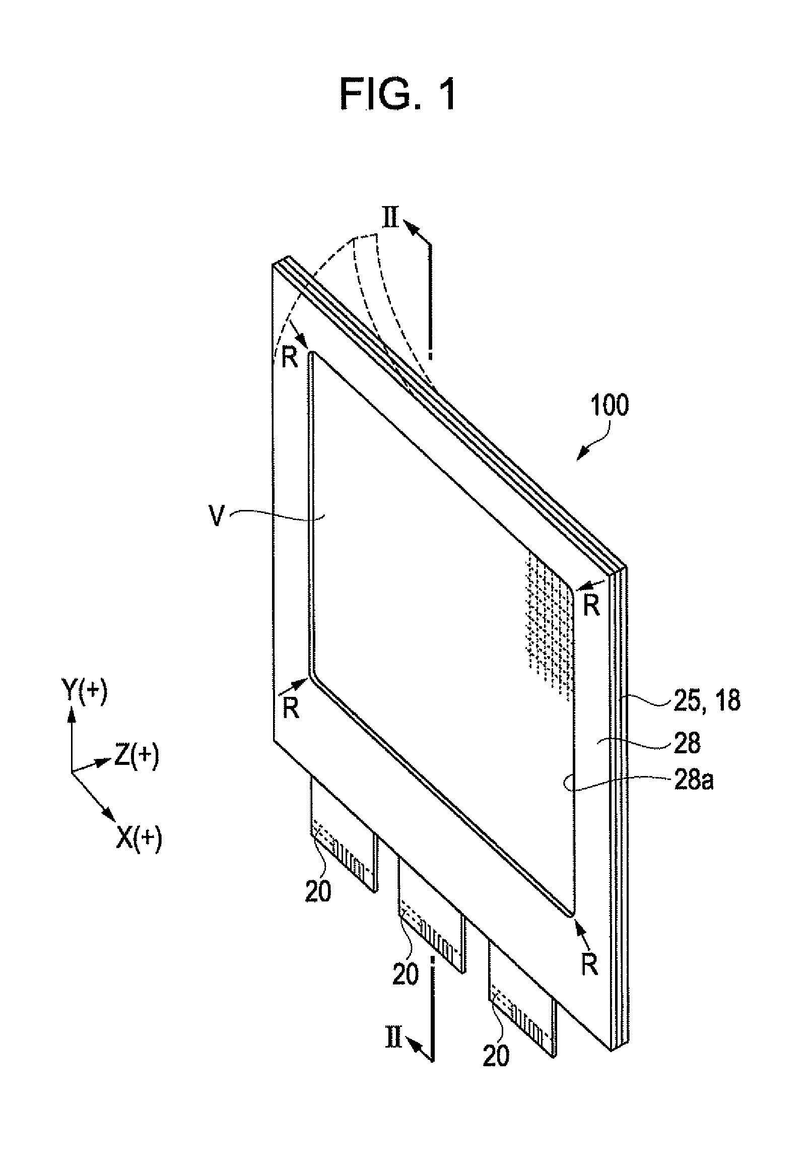
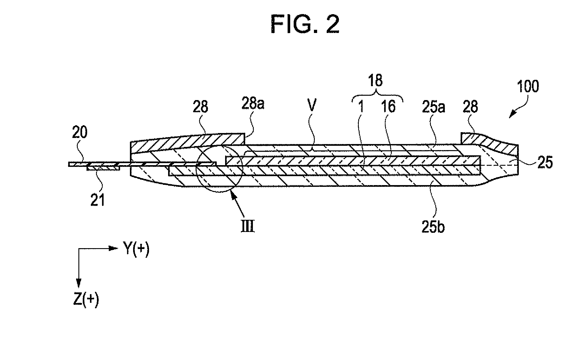
[0115]FIG. 1 is a perspective view of a display according to a first embodiment of the invention. FIG. 2 is a sectional side view of the display taken along the line II-II in FIG. 1.

[0116]The following is an outline of a display 100, which is an electro-optical device according to a first embodiment of the invention.

[0117]As illustrated in FIGS. 1 and 2, the display 100 is a flexible organic EL display that includes a display panel 18, which is a thin organic EL panel, between a first resin film 25a and a second resin film 25b. This laminate structure or the display panel 18 in a stacked form is hereinafter also referred to as a laminate structure 25.

[0118]The display panel 18 includes a display area V composed of a matrix of pixels. Each of a pair of substrates constituting the display panel 18 has a thickness of 100 μm or less to ensure great flexibility. The display area V includes arrays of red (R), green (G), and blue (B) pixels. Light beams from the pixels fo...

second embodiment

[0209]FIG. 7 is a cross-sectional view of a display according to a second embodiment and corresponds to FIG. 2.

[0210]A display 110 according to the second embodiment will be described below. The same components as in the first embodiment are denoted by the same reference numerals and will not be further described.

[0211]In addition to the components of the display 100 according to the first embodiment, the display 110 further includes an optical film 35 and a second reinforcing member 29 on the back side of the laminate structure 25. Except for this, the description in the first embodiment substantially applies to the present embodiment.

[0212]In addition to the reinforcing member 28 (hereinafter also referred to as a first reinforcing member 28) on the front side of the laminate structure 25, the display 110 further includes the frame-shaped second reinforcing member 29 on the back side of the laminate structure 25. The second reinforcing member 29 has an opening 29a corresponding to...

third embodiment

[0231]FIG. 8 is a cross-sectional view of a display according to a third embodiment and corresponds to FIG. 7.

[0232]A display 120 according to the third embodiment will be described below. The same components as in the second embodiment are denoted by the same reference numerals and will not be further described.

[0233]The display 120 according to the present embodiment is different from the display 110 according to the second embodiment only in the structure of the second reinforcing member on the back side of the laminate structure 25. More specifically, the display 120 includes a second reinforcing member 30 having no opening (hole) on the back side of the laminate structure 25. The optical film 35 has a larger size than the display area V, and the first reinforcing member 28 is laid on the periphery of the optical film 35. Except those, the description in the second embodiment applies to the present embodiment.

[0234]The display 120 includes the first reinforcing member 28 on the ...


PUM


Abstract

An electro-optical device includes a display panel having an electro-optical layer, a first resin film stacked on the display panel to cover a first surface on the side of a display area of the display panel, and a second resin film stacked on the display panel to cover a second surface opposite the first surface, and at least one reinforcing member disposed on at least one of the first resin film and the second resin film.

Description

BACKGROUND[0001]1. Technical Field[0002]The present invention relates to an electro-optical device, an electronic device, and an illumination apparatus.[0003]2. Related Art[0004]Flat-panel displays for use in thin television sets and mobile phones are required to be of low profile and light weight. In recent years, flexible flat-panel displays have been proposed to develop new markets.[0005]For example, JP-A-2005-19082 discloses an organic EL display that includes an organic electroluminescence (EL) layer between two glass substrates each having a thickness as small as 100 μm or less. JP-A-2005-19082 also discloses that the organic EL display may include resin reinforcing layers on outer surfaces of the front and back glass substrates to compensate for the insufficient strength resulting from the reduced thickness.[0006]As illustrated in FIG. 34, Japanese Patent No. 4,131,639 discloses a liquid crystal display 400 that includes a liquid crystal panel 90 composed of a pair of thin gl...

Claims


Application Information

Patent Timeline
Patent Type & Authority Applications(United States)
IPC IPC(8): H01L51/52H01J1/62
CPCB60Q3/0253B60Q3/0283H05B33/10B64D2011/0038H01L51/5237B64D47/02B60Q3/44B60Q3/745H10K50/841H10K50/8426H10K50/844H10K59/00H10K50/84
Inventor HAYASHI, KENJISHITAGAMI, KOZOKEZUKA, MISAKO
Owner ELEMENT CAPITAL COMMERCIAL CO PTE LTD
Why Eureka
Try Eureka