
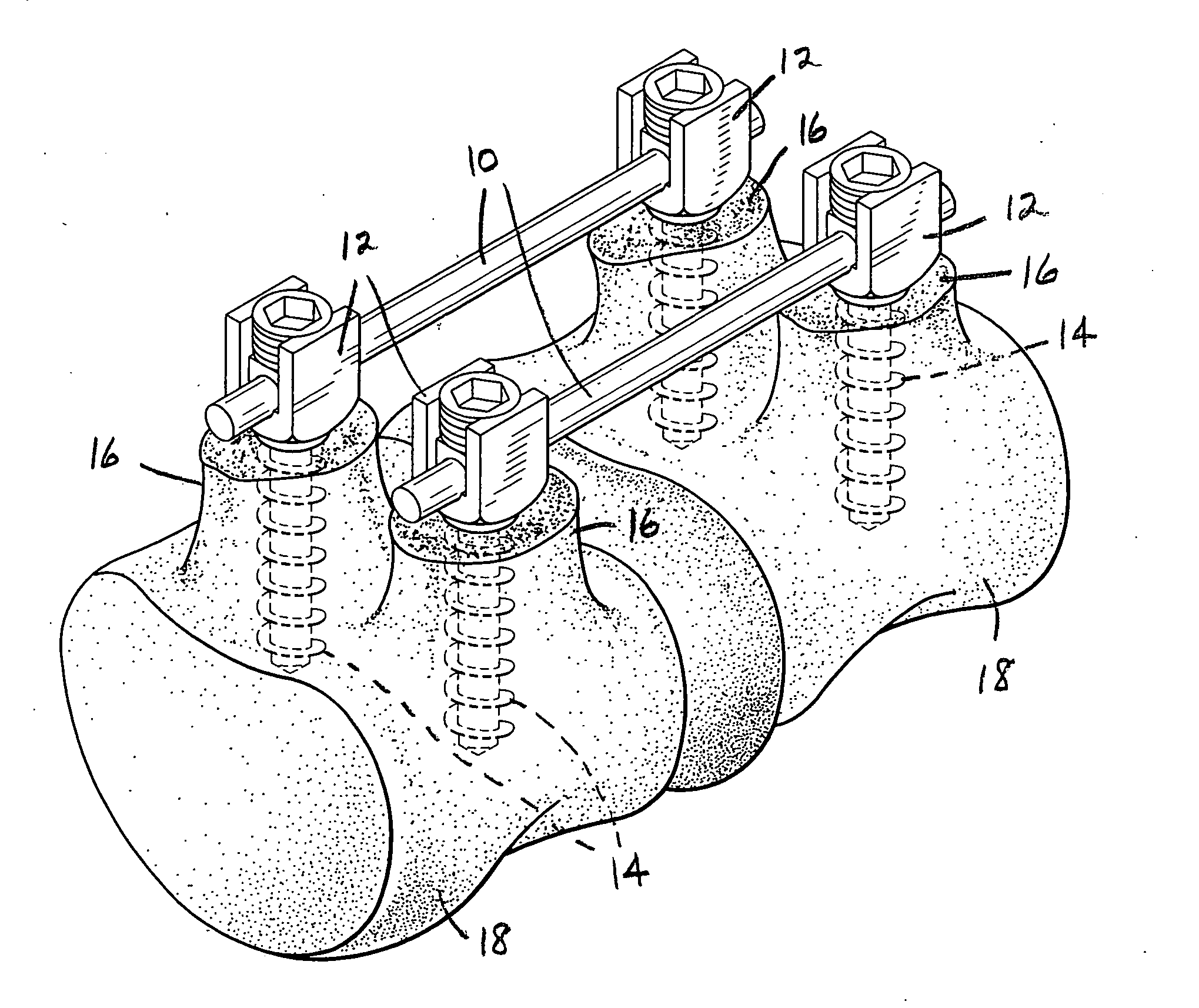
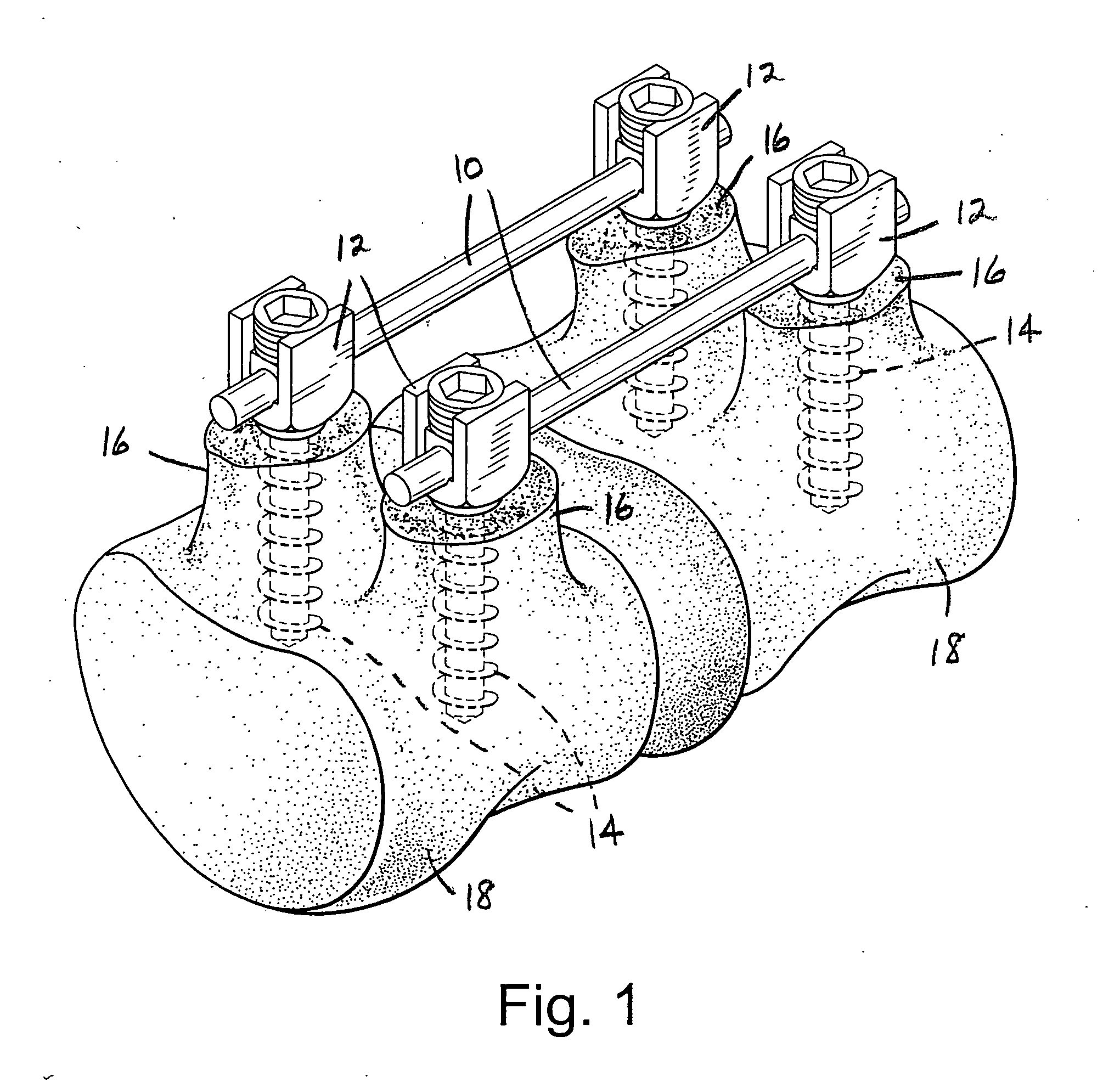
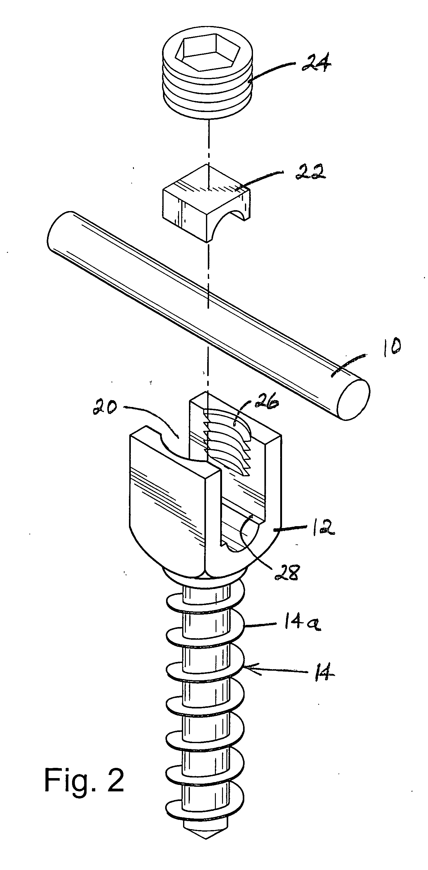
Apparatus and method for flexible spinal fixation

a technology of flexible fixation and apparatus, applied in the field of apparatus and method for flexible fixation of vertebral columns, can solve the problems of significant patient disability, loss of support by this instrumentation, and inordinate stress and degeneration of remaining segments, and achieve the effect of low stretch and high tensile strength

Inactive Publication Date: 2007-10-04
HOLT DEV
View PDF21 Cites 141 Cited by
  • Summary
  • Abstract
  • Description
  • Claims
  • Application Information

AI Technical Summary

Benefits of technology

[0008] The flexible composite connecting rod comprises a rod member formed of a suitable, flexible, biocompatible material, such as polyurethane, UHMW polyethylene, PEEK or Teflon, having a desired compression strength. A high tensile strength, low stretch, flexible, biocompatible reinforcing element in, e.g., cord or fabric form is encased and bonded to the rod member and extends longitudinally through the entire length thereof. A single large cord, multiple cords, a woven tube or the like may be used as the reinforcing element which may formed of any suitable material, such as Kevlar, polyethylene, polyurethane, Teflon fiber, carbon fiber or stainless steel. The composite connecting rod may be constructed to provide varying degrees of flexibility depending on the particular patient application.

Problems solved by technology

It has been found that the use of fusion in many cases results in significant patient disability.
By fusing vertebrae, the remaining segments are subject to inordinately high stress and degeneration.
This phenomenon usually produces loosening of the points of attachment for the implanted hardware and a resulting loss of support by this instrumentation unless fusion occurs.
These combined procedures involve extensive surgery, substantial blood loss and high costs.
Following such a procedure, patients are usually disabled for long periods of time.
This substantially rigid design makes perfect alignment nearly impossible and resulting stresses are passed to the bone.
The surgeon must bend and manipulate the rigid components for the best possible alignment, which is difficult and time consuming and can result in decreased fatigue strength of the deformed metal.
The stress imparted on components in addition to stresses applied by patient movement can lead to fatigue failure of metal components.
However, this system is difficult to align and tension, and requires cutting the tube to length during the surgical procedure.

Method used


Image

  • Apparatus and method for flexible spinal fixation
  • Apparatus and method for flexible spinal fixation
  • Apparatus and method for flexible spinal fixation

Examples


second embodiment

[0026]FIG. 7 illustrates the flexible composite connecting rod 10′ (or 110 or 210) wherein a single large flexible reinforcing element 10c extends longitudinally through the entire length of the rod member 10d and is bonded thereto. In this embodiment, the rod member 10d and flexible reinforcing element 10c may be formed of any construction or suitable materials as hereinbefore described.

third embodiment

[0027]FIG. 8 discloses the flexible composite connecting rod 10″ (or 110 or 210) which comprises a rod member 10e and a tubular flexible reinforcing element 10f extending through the entire length thereof and connected thereto. Within the scope of the present invention, the tubular element 10f may be disposed within a central elongated opening in the rod member 10e, or may be embedded in the central portion of a solid rod member. The rod member 10e and tubular reinforcing element 10f may be of any suitable construction or materials as hereinbefore described.


PUM


Abstract

Apparatus for connecting and stabilizing adjacent vertebral segments, comprising a flexible composite connecting rod extending between the segments, and connection devices for connecting the rod to the vertebral segments. The rod comprises a rod member formed of a flexible plastic material having a predetermined compression strength, and a high tensile strength, low stretch, flexible reinforcing element extending longitudinally through the entire length of the rod member and being bonded thereto. The reinforcing element may be in the form of a single cord, rope, braid or monofilament, a plurality of substantially parallel cords, ropes, braids or monofilaments, or a tubular cord, rope or braid extending through the rod member.

Description

FIELD OF THE INVENTION [0001] The present invention relates to an apparatus and method for spinal fixation and, more particularly, to such an apparatus and method for flexible stabilization of a vertebral column or the like. DESCRIPTION OF THE RELATED PRIOR ART [0002] Stabilization of vertebral columns by instrumentation devices and / or bone material to facilitate a bone fusion is a common and long practiced surgical technique. Fusion is the permanent internal fixation of part or all of the intervertebral joints, an inter-vertebral joint being composed of two adjacent vertebrae and their posterior bony elements connected by an intervertebral disc, ligaments, and two facet joint capsules. It has been found that the use of fusion in many cases results in significant patient disability. By fusing vertebrae, the remaining segments are subject to inordinately high stress and degeneration. [0003] When spine stabilization involves mechanical instrumentation, significant forces are directly ...

Claims


Application Information

Patent Timeline
Patent Type & Authority Applications(United States)
IPC IPC(8): A61F2/30
CPCA61B17/7029A61B17/704A61B17/7032A61B17/7031
Inventor HOLT, RICHARD
Owner HOLT DEV
Learn More