Lighting device

a technology for lighting devices and heat dissipation schemes, applied in semiconductor devices, semiconductor devices for light sources, lighting and heating apparatus, etc., can solve problems such as waste heat and the need for efficient heat dissipation, and achieve the effect of reducing the cost of lighting equipment, and improving the efficiency of lighting equipmen

Active Publication Date: 2008-02-28
HONG KONG APPLIED SCI & TECH RES INST
View PDF9 Cites 83 Cited by
  • Summary
  • Abstract
  • Description
  • Claims
  • Application Information

AI Technical Summary

Benefits of technology

[0010]By creating a heat dissipating structure which is located rearwards of the light sources, and by configuring the heat dissipating structure to promot

Problems solved by technology

However, as the density of light-emitting sources increases, the problem of waste heat and the need of efficient heat dissipation becomes an important issue.
Therefore, the problem of efficient heat dissipation management is especially noticeable for lighting devices comprising LEDs as lighting

Method used


Image

  • Lighting device
  • Lighting device
  • Lighting device

Examples


Embodiment Construction

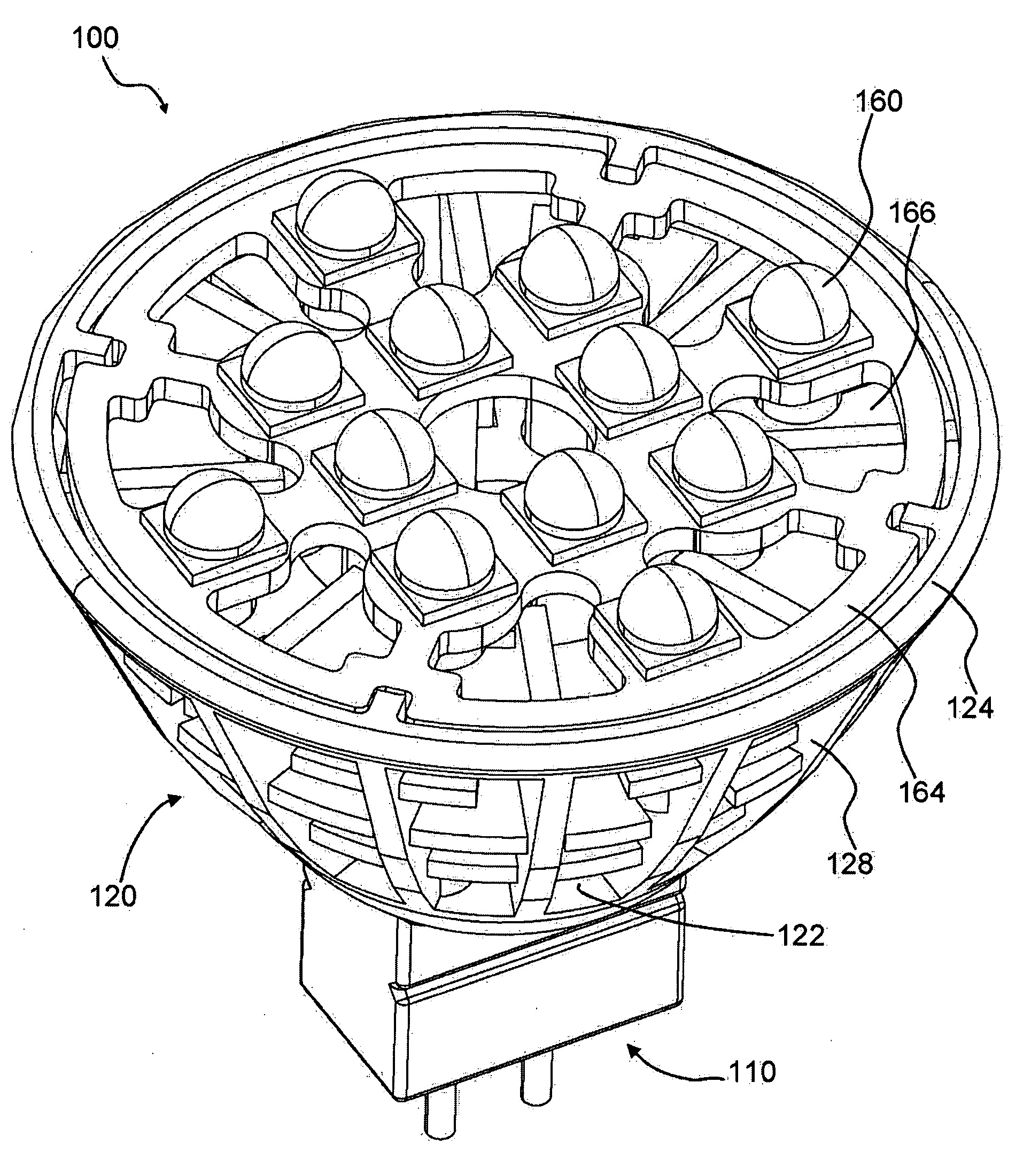
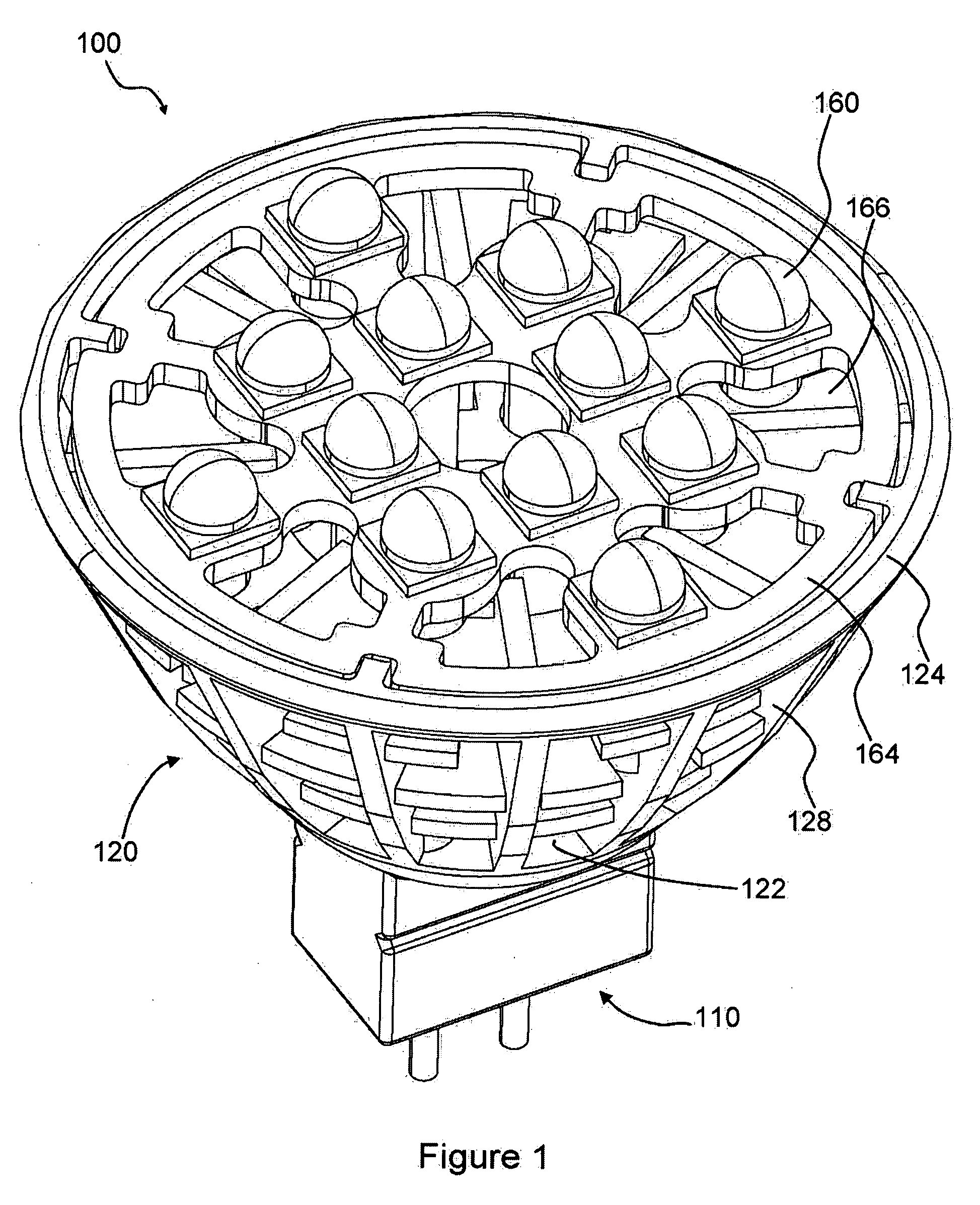
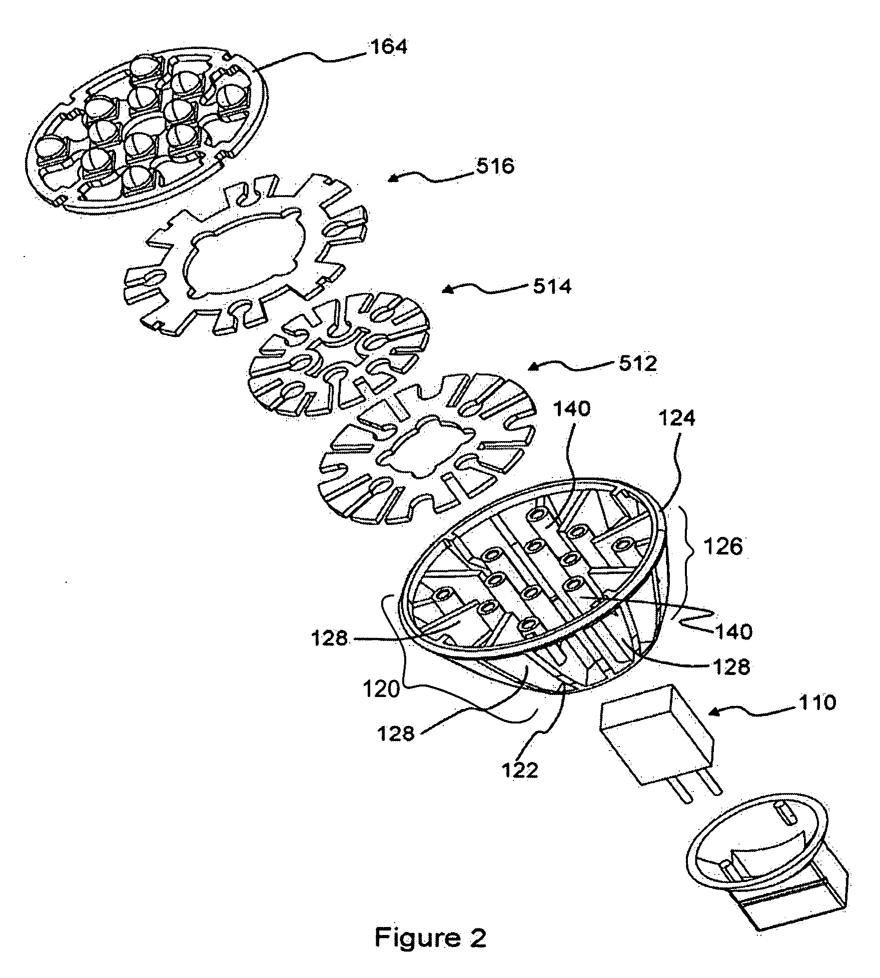
[0047]An exemplary embodiment of this invention of a light device 100 as depicted in FIGS. 1 to 9 comprises a plurality of light-emitting diodes (LEDs) on a lamp fixture. The lamp fixture is compatible to the commonly known MR-16 lamp fixture, as a convenient example. The lamp fixture comprises a lamp body, which has a main housing on which a plurality of LEDs is mounted, and a lamp base, which has an electrical connector for connecting to the power supply (not shown). In the example device of FIG. 1, the electrical connector is a bayonet-type plug 110 with two, positive and negative, electrodes.

[0048]The lamp body comprises a thermally conductive main housing 120 on which a plurality of column-shaped or finger-shaped elongate protrusions 140 is formed. As shown in the Figures, the main housing is cup-shaped, and comprises a base portion 122, a front frame or front flange 124 which is distal from the base portion and defines a main aperture, and a peripheral housing 126 interconnect...


PUM


Abstract

A lighting device contains a plurality of light emitting sources mounted on a thermally conductive housing and electrically connected to a circuit board. The housing includes a base portion which is spaced apart from the circuit board, and an intermediate heat dissipation structure which is disposed between the circuit board and the base portion of the housing, for promoting cooling by convection. The plurality of light emitting sources are in thermal communication with the intermediate heat dissipation structure.

Description

FIELD OF THE INVENTION[0001]This invention relates to lighting devices, and more particularly, to lighting devices comprising a plurality of discrete light emission components mounted on a common housing. More specifically, other not solely limited thereto, this invention relates to a lighting device comprising a plurality of light-emitting diodes (LEDs) on a housing.BACKGROUND OF THE INVENTION[0002]Lighting devices with a high luminosity density are known to be useful. A plurality of light emitting sources is usually assembled in a housing in order to increase luminosity density. However, as the density of light-emitting sources increases, the problem of waste heat and the need of efficient heat dissipation becomes an important issue.[0003]LEDs (Light-emitting diodes) have become a popular choice of light-emitting sources due to its high electro-optical conversion efficiency as well as their long operating life span. However, it is well-known that the electro-optical conversion eff...

Claims


Application Information

Patent Timeline
IPC IPC(8): F21V9/00H05K7/20
CPCF21Y2101/02F21K9/137H01L2224/48091F21V29/89F21V29/83F21V29/507F21V29/767F21V29/777H01L2924/00014F21K9/233F21Y2115/10
Inventor LU, MINGWU, KAI CHIUPANG, CHAK HAU
Owner HONG KONG APPLIED SCI & TECH RES INST
Why Eureka
Try Eureka