Electric machine comprising a cooled rotor

A rotor, coolant technology used in vehicle drive trains. field, can solve problems such as reducing motor efficiency

Inactive Publication Date: 2016-11-23
ZF FRIEDRICHSHAFEN AG
View PDF4 Cites 2 Cited by
  • Summary
  • Abstract
  • Description
  • Claims
  • Application Information

AI Technical Summary

Problems solved by technology

A disadvantage in known electrical machines is that the coolant from the cooling channels reaches the stator or the winding heads of the stator, so that the coolant can also easily reach the air gap between the rotor and the stator
Coolant entering the air gap causes shear forces between rotor and stator, which generate a braking torque on the rotor and thus reduce the efficiency of the electric machine

Method used


Image

  • Electric machine comprising a cooled rotor
  • Electric machine comprising a cooled rotor
  • Electric machine comprising a cooled rotor

Examples


Embodiment Construction

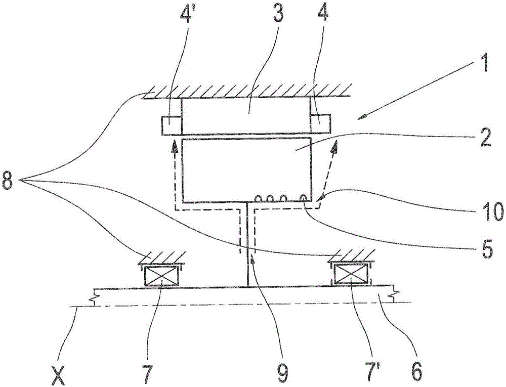
[0023] figure 1 A longitudinal section through the electric machine 1 is shown. Electric machine 1 has a stator 3 and a rotor 2 . The rotor 2 is firmly connected to the driven shaft 6 of the motor 1 . The rotor 2 and the driven shaft 6 are rotatably supported in the housing 8 of the electric machine 1 via bearings 7, 7'. The stator 3 is firmly connected to the housing 8 . The stator 3 has a plurality of electrical windings of electrical conductors, for example copper wires, and the stator 3 has winding heads 4, 4' on each axial end side. The rotor 2 is arranged radially inside the stator 3, so the motor 1 is an internal mover machine.

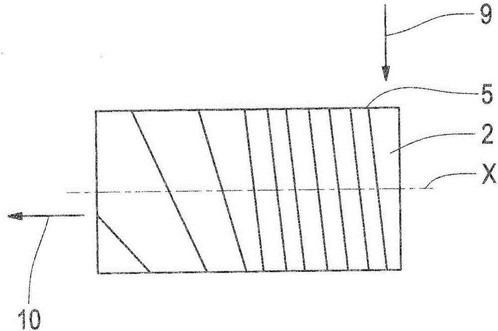
[0024] The rotor 2 has a liquid cooling with at least cooling channels 5 in the rotor 2 . The liquid cooling provides that the coolant is introduced radially from the output shaft 6 in the direction of the rotor 2 into the cooling channel 5 . The coolant flows through the flow channels 5 along the radial inner side of the rotor 2 towards ...


PUM


Abstract

The invention relates to an electric machine (1) comprising a stator (3) and comprising a rotor (2), wherein the stator (3) has windings having at least one end-side end winding (4, 4'), and wherein the rotor (2) has at least one at least partially helical cooling channel (5), which is open axially in the direction of this end winding (4, 4') so that coolant is conveyed out of the cooling channel (5) in the direction of this end winding (4, 4') on rotation of the rotor (2). In this case, provision is made for the rotor (2) and the at least one cooling channel (5) to be embodied in such a way that the coolant is flung out of the cooling channel (5) and the rotor (2) axially beyond this end winding (4, 4') on rotation of the rotor (2). The invention also relates to a vehicle drive train comprising such an electric machine (1) as traction drive.

Description

technical field [0001] The invention relates to an electrical machine with a stator and a rotor, wherein the stator has a winding with at least one end-side winding head. The rotor has at least one cooling channel running at least partially helically, which is open axially in the direction of the winding head, so that coolant is conveyed from the cooling channel and the rotor in the direction of the winding head during rotation of the rotor. The invention also relates to a vehicle drive train with such an electric machine as traction drive. Background technique [0002] Such an electric machine is known from DE 10 2011 079 165 A1. Another electric machine with a liquid-cooled rotor is known from DE 11 2010 005 824 T5, in which no helically running cooling channels are provided in the rotor. A disadvantage of the known electric machine is that the coolant from the cooling channel reaches the stator or the winding ends of the stator, so that the coolant can also easily reach...

Claims


Application Information

Patent Timeline
IPC IPC(8): H02K1/32
CPCH02K1/32H02K9/19H02K1/12H02K1/2706H02K7/08H02K7/116
Inventor 马蒂亚斯·尼奇安德烈亚斯·霍尔舍
Owner ZF FRIEDRICHSHAFEN AG
Why Eureka
Try Eureka