Frequency-locking phase-locking and deploying structure of different-cavity magnetron

A technology of frequency-locking, phase-locking, and magnetron, which is applied to the coupling device of the time-of-flight electron tube and the circuit components of the time-of-flight electron tube. It can solve the problem of low power capacity and achieve high power and high production value. , is conducive to the effect of debugging and assembly

Pending Publication Date: 2022-05-10
UNIV OF ELECTRONIC SCI & TECH OF CHINA
View PDF8 Cites 0 Cited by
  • Summary
  • Abstract
  • Description
  • Claims
  • Application Information

AI Technical Summary

Problems solved by technology

[0005] In view of the above-mentioned deficiencies in the prior art, the frequency-locked phase-locked and deployment structure of the different-cavity magnetron provided by the present invention solves the problem of low power capacity existing in the different-cavity magnetron

Method used


Image

  • Frequency-locking phase-locking and deploying structure of different-cavity magnetron
  • Frequency-locking phase-locking and deploying structure of different-cavity magnetron
  • Frequency-locking phase-locking and deploying structure of different-cavity magnetron

Examples


Embodiment 1

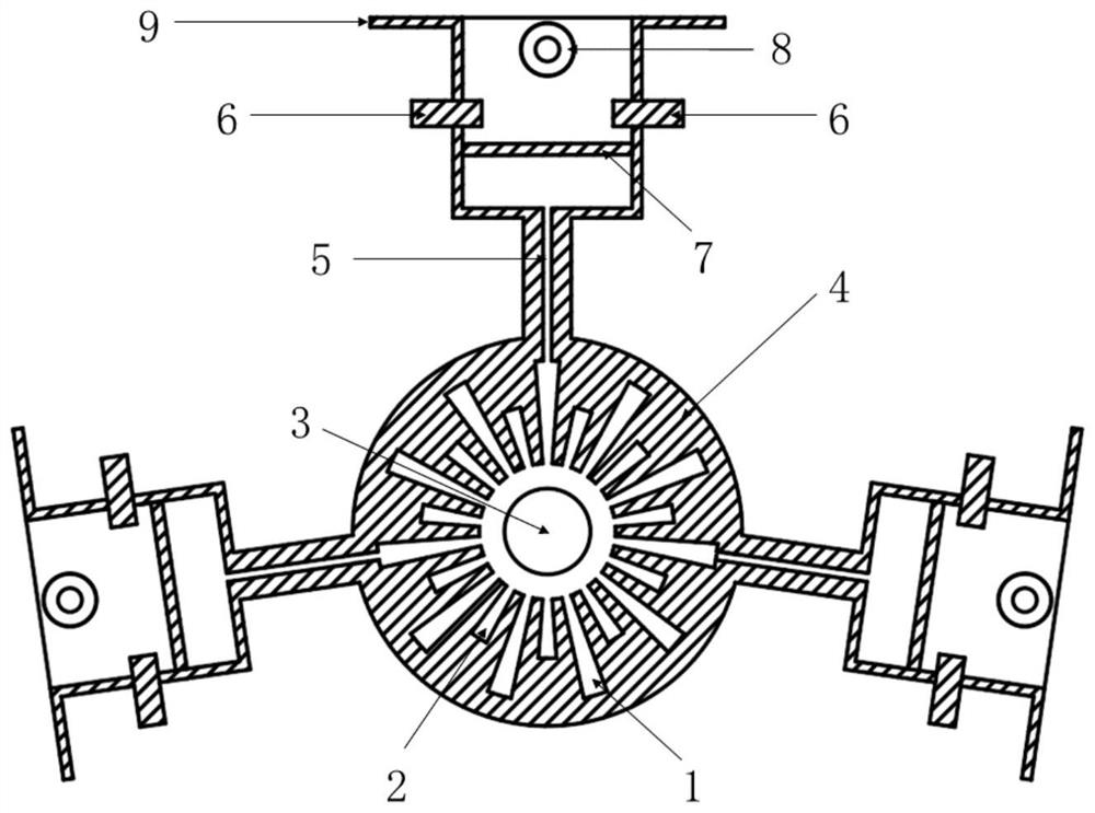
[0031] The embodiment of the present invention provides a frequency-locked phase-locked and deployment structure of different-cavity magnetrons, such as figure 1 As shown, it includes an adjustable pin 6 and a coaxial attenuation coupling port 8 arranged in the output structure of the different-cavity magnetron;

[0032] The adjustable pin 6 is used to adjust the working state of the different-cavity magnetron and the energy distribution among the output structures; the coaxial attenuation coupling port 8 is used to monitor the output or injected energy;

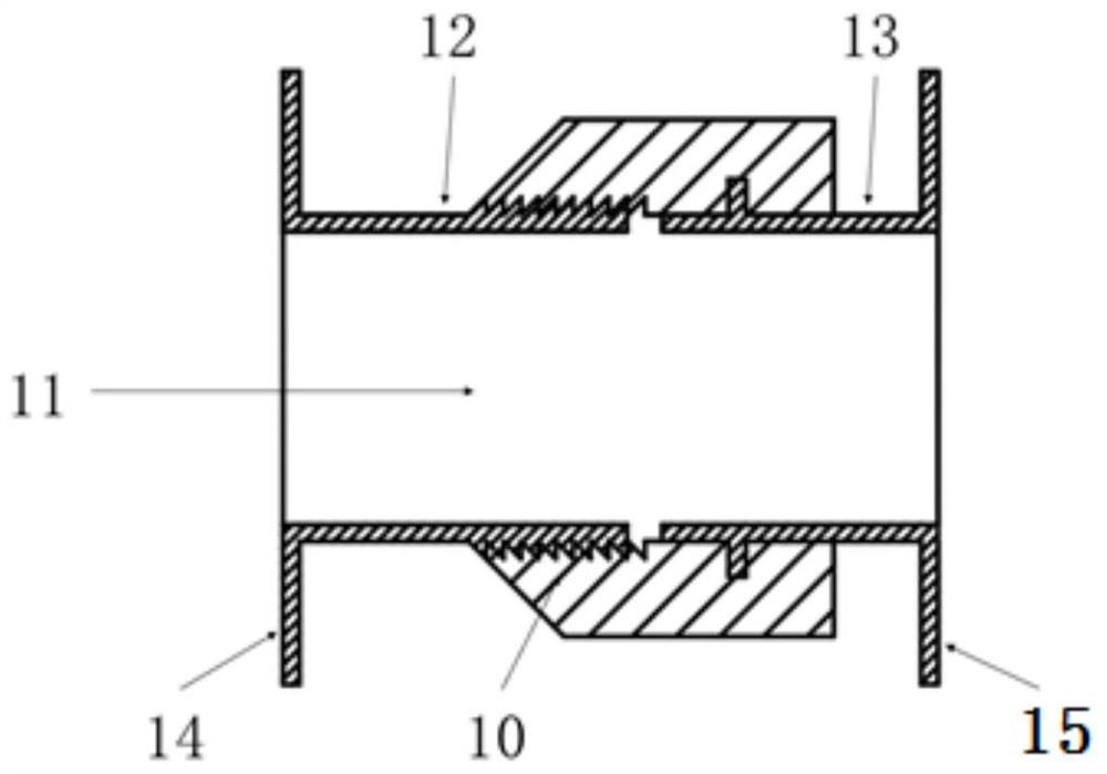
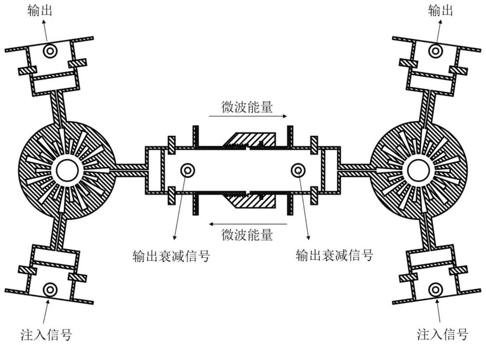
[0033] The output structure of the different-cavity magnetron is connected with other different-cavity magnetrons through a length-adjustable rectangular waveguide.

[0034] In the embodiment of the present invention, based on the above structural settings, a series of different-cavity magnetrons are closely coupled. The most important feature is that because the different-cavity magnetrons are greatly affected by the comple...

Embodiment 3

[0054] The size of this embodiment is designed according to the working frequency f=35GHz. In order to improve the quality factor, pure copper with high conductivity should be used as the manufacturing material. After the processing is completed, the surface can be plated with silver or gold. The radius of the top of the large anode resonant cavity 1 is 3-4mm, the radius of the top of the small anode resonant cavity 2 is 2-3mm, the radius of the cathode 3 is 1-2mm, the wall thickness of the anode inner conductor 4 is 1-2mm, and the impedance transformer 5 The height is 3-4mm, the width is 0.1-0.5mm, the radius of the symmetrical tuning piston is 0.5-1.5mm, the position is 2-3mm away from the end of the rectangular waveguide, the depth is 0.2-1mm, and the thickness of the window is 0.5-1mm. The outer radius of the shaft attenuation coupling port is 0.6-0.8mm, and the inner radius is 0.4-0.6mm. The working voltage of the different-cavity magnetron is 10-20kV, the magnetic field ...


PUM


Abstract

The invention discloses a frequency and phase locking and deploying structure of a different-cavity magnetron. The frequency and phase locking and deploying structure comprises an adjustable pin and a coaxial attenuation coupling port which are arranged in an output structure of the different-cavity magnetron, the adjustable pin is used for adjusting the working state of the different-cavity magnetron and energy distribution among the output structures; the coaxial attenuation coupling port is used for monitoring output or injected energy; and the output structure of the different-cavity magnetron is connected with other different-cavity magnetrons through a length-adjustable rectangular waveguide. According to the invention, the microwave output signals of a plurality of different-cavity magnetrons are coherent, the output signals can be used for power synthesis, the structure enables the output signals of large-scale different-cavity magnetrons to be coherent, and the equivalent omnidirectional radiation power of the coherent signals is increased along with the number N square of the magnetrons. Therefore, the different-cavity magnetron is used for frequency locking and phase locking, the power of the microwave source is improved, and high research value and economic benefits are achieved as well.

Description

technical field [0001] The invention belongs to the technical field of microwave power sources in vacuum electronic devices, and in particular relates to a frequency-locking, phase-locking and deployment structure of a different-cavity magnetron. Background technique [0002] Today, microwave technology has been widely used in the preparation of industrial materials, food sterilization, chemical production and so on. As a new type of energy technology, microwave is not only widely used in military fields such as radar communication, electronic countermeasures, and aerospace guidance, but also gradually used in civilian fields such as industrial heating, biomedicine, and lossless detection. [0003] In the field of vacuum electronic devices, the magnetron is a reentrant resonant cross-field oscillator and a high-power source in microwave technology. Its main features are high efficiency and low working voltage, followed by its small size, light weight, convenient use, reliab...

Claims


Application Information

Patent Timeline
IPC IPC(8): H01J23/36H01J23/18
CPCH01J23/36H01J23/18
Inventor 王彬蒙林殷勇李海龙宋岷生
Owner UNIV OF ELECTRONIC SCI & TECH OF CHINA
Why Eureka
Try Eureka