Tetrahedral mesh virtual cutting method based on route separation

A technology of tetrahedral mesh and cutting method, applied in the field of computer science, can solve problems such as complex steps, slow finite element calculation, violation of the law of conservation of mass, etc., to achieve the effect of improving stability and maintaining calculation speed

Inactive Publication Date: 2016-11-30
HARBIN UNIV OF SCI & TECH
View PDF3 Cites 5 Cited by
  • Summary
  • Abstract
  • Description
  • Claims
  • Application Information

AI Technical Summary

Problems solved by technology

The mass point-spring model is simple and fast to calculate, and only needs to update the topology when cutting or resetting the mesh, which can easily simulate the cutting of objects, but its simple model determines that the accuracy of deformation cannot be guaranteed during the operation
The finite element model can accurately simulate the deformation with physical meaning, but the quantity and quality of the tetrahedral mesh will have a direct impact on the computational stability of the finite element
The speed and quality of cutting have a great impact on virtual surgery. The main task of cutting is to meet the change of model topology under cutting conditions. The simplest cutting method is the removal method. Although the calculation amount is small and the implementation is simple, However, the law of conservation of mass is violated, and the cutting boundary is jagged and aliased
The vertex copy needs to be accurately recorded and will produce irregular shapes due to the copied position, which will lead to subsequent reprocessing, making the steps complicated, easy to generate small meshes, and affecting finite element calculations
Similarly, the cutting method of subdividing tetrahedral grids is also prone to irregular grids. In order to eliminate irregular grids, it is necessary to split multiple times on a tetrahedral grid to generate multiple sub-tetrahedrons. Under continuous cutting, It is easy to slow down the finite element calculation, and due to the existence of small tetrahedron, it will lead to the instability of finite element calculation

Method used


Image

  • Tetrahedral mesh virtual cutting method based on route separation
  • Tetrahedral mesh virtual cutting method based on route separation
  • Tetrahedral mesh virtual cutting method based on route separation

Examples


Embodiment Construction

[0022] In order to describe the present invention more specifically, the tetrahedral grid virtual cutting method of the present invention will be described in detail below in conjunction with the accompanying drawings and specific embodiments.

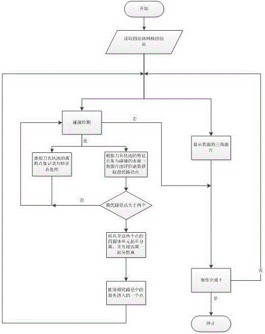
[0023] Such as figure 1 As shown, a virtual cutting method of tetrahedral mesh based on path separation includes the following steps.

[0024] (1) Read the data of the tetrahedral grid to obtain the surface triangular patch set of the tetrahedral grid;

[0025] Read the tetrahedral data, and generate a collection of tetrahedral meshes, a collection of triangular patches, and a collection of points.

[0026] (2) The thread that starts the collision detection and the thread that assembles the triangles on the display surface to the screen;

[0027] Start two threads, which are always running during the whole process of operation, and the threads will not exit until the user stops using the program. They are the collision detection thr...


PUM


Abstract

A tetrahedral mesh virtual cutting method based on route separation comprises the steps that 1, data of a tetrahedral mesh is read, and a surface triangular patch set of the tetrahedral mesh is obtained; 2, a collision detecting thread is started, and a thread from the surface triangular patch set to a screen is displayed; 3, after collision detection occurs, track discretization of a tool is started, feature point processing is carried out, and meanwhile selection of an optimal route is started; 4, a tetrahedron shared by two first points on the optimal route is separated; 5, the two points in the step 4 are deleted. In the cutting process, each colliding patch is evaluated through an evaluation function, the optimal point is selected to serve as a route of a cutting track, and then tetrahedron separation is carried out; due to the fact that only topological separation exists in the cutting process, and no pathological tetrahedrons are generated, the stability of finite element computing is improved, the number of the tetrahedrons is not increased, and the computing speed is kept.

Description

technical field [0001] The invention belongs to the technical field of computer science, and more specifically relates to a method for virtual cutting of tetrahedron grids based on path separation. Background technique [0002] The cutting of soft tissue is an important part of virtual surgery in the medical field. It not only needs to meet the fidelity, but also must follow the physical characteristics and real-time changes of biological tissues, which is a very challenging subject. [0003] At present, the soft tissue models at home and abroad are more representative of the mass-spring model and the finite element model. The mass point-spring model is simple and quick to calculate, and only needs to update the topology when cutting or resetting the mesh, which can easily simulate the cutting of objects, but its simple model determines that the accuracy of deformation cannot be guaranteed during the operation. The finite element model can accurately simulate the deformatio...

Claims


Application Information

Patent Timeline
Patent Type & Authority Applications(China)
IPC IPC(8): G06F19/00
CPCG16H50/50
Inventor 王沫楠毛志勇陈少勇李荣鹏
Owner HARBIN UNIV OF SCI & TECH
Why Eureka
Try Eureka