Self-discharge regulator for display

A voltage stabilizer and self-discharge technology, applied in static indicators, instruments, etc., can solve problems such as inability to release, the first voltage V1 is out of alignment, and achieve the effect of improving accuracy

Active Publication Date: 2018-08-14
ULTRA CHIP INC
View PDF6 Cites 0 Cited by
  • Summary
  • Abstract
  • Description
  • Claims
  • Application Information

AI Technical Summary

Problems solved by technology

[0005] However, in the voltage stabilizing circuit 1, since the potential of the second voltage V2 is higher than that of the first voltage V1, the output voltage Vo is switched from the second voltage V2 to that of the first voltage V1. During the process, the excess charge originally stored in the output voltage Vo is released to the first voltage V1; and when the voltage is increased due to the charge injected into the first voltage V1, the injected charge cannot be released, so that the The voltage level of the first voltage V1 is raised and cannot be lowered back to the target voltage Vt, thus causing the first voltage V1 to be out of alignment

Method used


Image

  • Self-discharge regulator for display
  • Self-discharge regulator for display
  • Self-discharge regulator for display

Examples


Embodiment Construction

[0021] The following descriptions of the various embodiments refer to the accompanying drawings to illustrate specific embodiments in which the present invention can be practiced. Furthermore, the directional terms mentioned in the present invention are, for example, up, down, top, bottom, front, back, left, right, inside, outside, side, surrounding, central, horizontal, transverse, vertical, longitudinal, axial, The radial direction, the uppermost layer or the lowermost layer, etc. are only directions referring to the attached drawings. Therefore, the directional terms used are used to illustrate and understand the present invention, but not to limit the present invention.

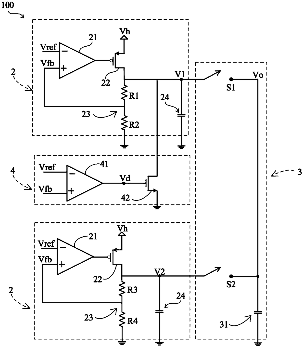
[0022] Please refer to image 3 , 4 As shown, it is an embodiment of the self-discharging voltage stabilizing device used in the display of the present invention. In this embodiment, a self-discharging voltage stabilizing device 100 is applied to the power management of the electrophoretic display, wher...


PUM


Abstract

The invention discloses a self-discharge voltage stabilizing device for a display, including a linear voltage stabilizing unit, a switch unit and a self-discharge unit. The self-discharge unit is electrically connected with an output end of a first transistor of a linear voltage stabilizing unit for improving the accuracy of the output voltage of the first transistor.

Description

technical field [0001] The invention relates to a self-discharging voltage stabilizing device for a display, in particular to a self-discharging voltage stabilizing device applied to the power management of a display. Background technique [0002] In the prior art, LDO regulators have been widely used in power management of portable electronic devices (such as monitors, mobile phones, personal digital assistants (PDAs), digital cameras, or notebook computers, etc.). [0003] see figure 1 As shown, it is a voltage stabilizing circuit 1 of the prior art, and the voltage-dropping voltage stabilizing circuit 1 includes two low-dropout voltage regulators 11, 12 and a switching unit 13, and each of the two low-dropout voltage regulators 11, 12 It includes a comparator 111, 121, a transistor 112, 122 and a feedback circuit 113, 123, wherein the comparators 111, 121 of the two low-dropout regulators 11, 12 can input a reference voltage Vref and a feedback circuit voltage Vfb, and ...

Claims


Application Information

Patent Timeline
Patent Type & Authority Patents(China)
IPC IPC(8): G09G3/34
CPCG09G3/348
Inventor 张正欣陈建廷邱联鼎洪扬程
Owner ULTRA CHIP INC
Why Eureka
Try Eureka