Dropping protection device and terminal
A drop protection, terminal technology, applied in the field of communications
- Summary
- Abstract
- Description
- Claims
- Application Information
AI Technical Summary
Problems solved by technology
Method used
Image

Examples
Example Embodiment
[0018] Example one
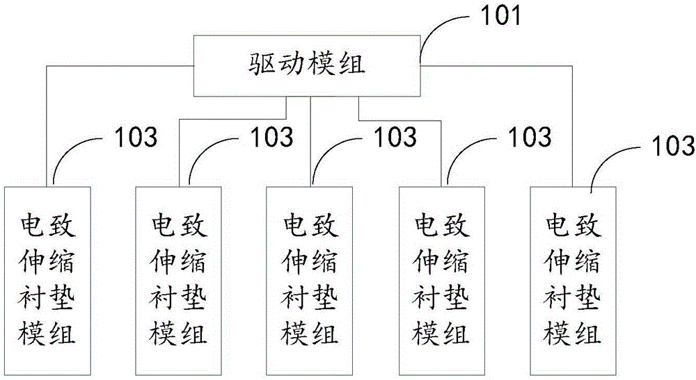
[0019] Please refer to figure 1 , figure 1 It is the principle block diagram of the fall protection device in the first preferred embodiment of the present invention. This first embodiment is designed in the background that the fall protection device is applied to a terminal housing such as a mobile terminal. When the terminal protection device is applied to other electronic equipment, the specific structure of the terminal housing can be modified accordingly.
[0020] In an embodiment, the fall protection device includes: a driving module 101 and at least one electrostrictive gasket module 103. The at least one electrostrictive gasket module 103 is respectively installed in a recessed structure on each outer wall surface of the terminal. The driving module 101 outputs a driving voltage to the electrostrictive component 103, so that the electrostrictive component 103 is deformed and elongated and protrudes from the concave structure on the outer wall surface o...
Example Embodiment
[0022] Example two
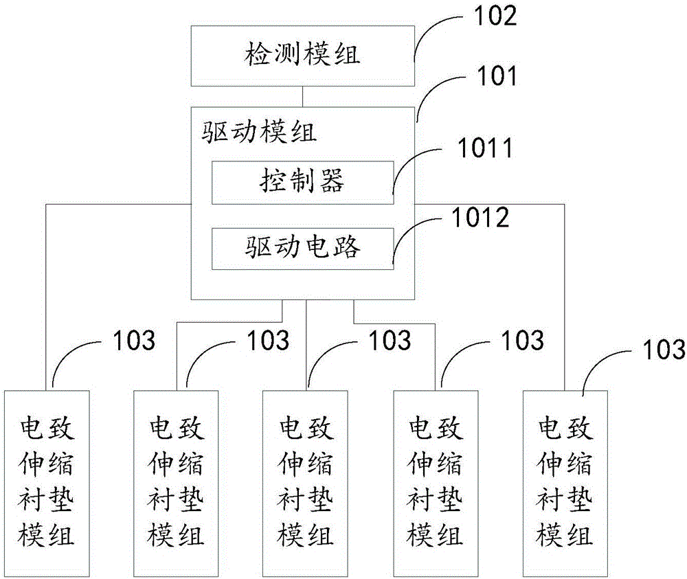
[0023] Please refer to figure 2 , figure 2 It is a functional block diagram of the fall protection device in the second preferred embodiment of the present invention. This second embodiment is designed on the background that the fall protection device is applied to terminal housings such as mobile terminals. When the fall protection device is applied to other electronic equipment When loading, the specific structure of the terminal housing can be modified accordingly. Also refer to image 3 , The fall protection device includes a drive module 101, a detection module 102, and at least one electrostrictive gasket module 103; the at least one electrostrictive gasket module 103 is respectively installed in a recessed structure on the outer wall of the terminal 200 in. Preferably, the at least one electrostrictive gasket module 103 is completely accommodated in the recessed structure on the outer wall surface of the terminal 200 when it is not deformed. Wherei...
Example Embodiment
[0031] Example three
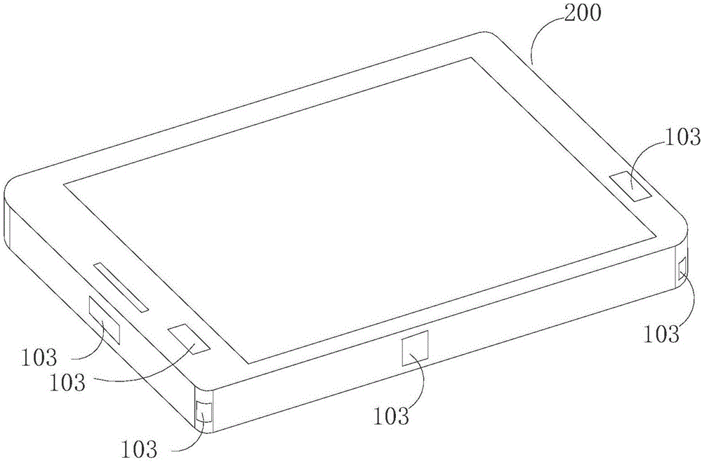
[0032] Please refer to Image 6 , Is a structural diagram of a terminal in a preferred embodiment of the present invention. This embodiment is designed on the background that the fall protection device is applied to a terminal housing such as a mobile terminal. When the terminal protection device is applied to other electronic equipment, the specific structure of the terminal housing can be modified accordingly. Also refer to Figure 7 In this embodiment, the terminal includes a terminal body 201 and the fall protection device in the first embodiment. The fall protection device is the fall protection device in the first embodiment, so its structure and principle are not repeated here.
[0033] The terminal body 201 has a plurality of outer wall surfaces, and each outer wall surface is provided with a recess structure 205. The recess structure 205 may be a groove or a through hole, and in this embodiment, it is a groove. The multiple electrostrictive gaske...
PUM
 Abstract
Description
Claims
Application Information
 - R&D Engineer
- R&D Manager
- IP Professional
- Industry Leading Data Capabilities
- Powerful AI technology
- Patent DNA Extraction
Browse by: Latest US Patents, China's latest patents, Technical Efficacy Thesaurus, Application Domain, Technology Topic.
© 2024 PatSnap. All rights reserved.Legal|Privacy policy|Modern Slavery Act Transparency Statement|Sitemap