
High-speed punching machine for punching spring pads

A punching machine and spring pad technology, applied in the field of spring pad production equipment, can solve the problems of complex equipment structure, increased production cost, low punching efficiency, etc., and achieve the effect of full automation and simple structure

Active Publication Date: 2018-03-20
瑞安市旭东冲压机械厂
View PDF6 Cites 0 Cited by
  • Summary
  • Abstract
  • Description
  • Claims
  • Application Information

AI Technical Summary

Problems solved by technology

[0002] In the manufacturing process of the spring pad, punching the metal wire is a very critical step. When punching the punching machine, the metal wire needs to be transported to the position of the cutter, and the cutter moves to punch the metal wire. In order to obtain the required spring pad, but the feeding and punching actions of traditional punching machines are often driven separately. This structure requires multiple driving devices, which makes the equipment structure more complicated and increases production costs. At the same time, the punching efficiency is relatively low. Low

Method used


Image

  • High-speed punching machine for punching spring pads
  • High-speed punching machine for punching spring pads

Examples


Embodiment Construction

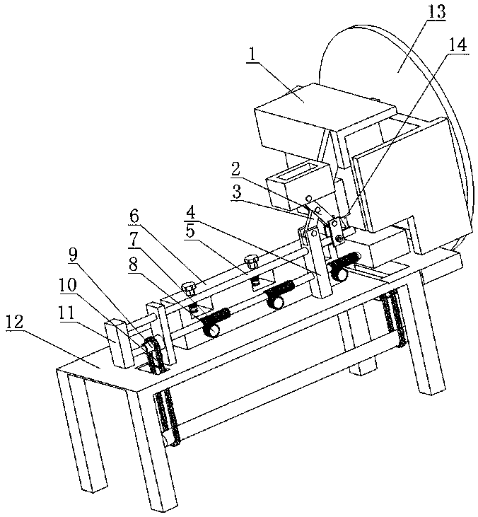
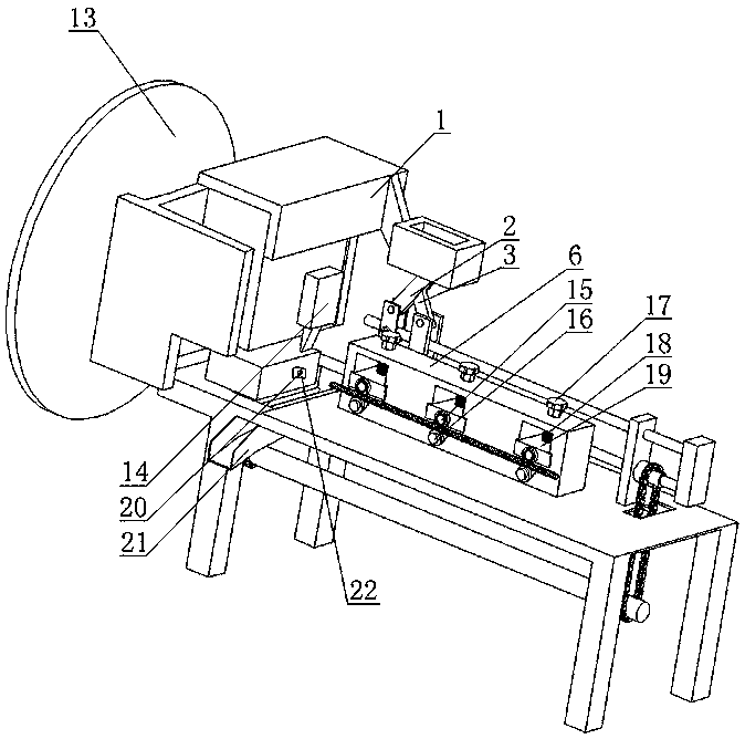
[0015] As shown in the figure, a high-speed punching machine for punching spring pads disclosed by the present invention includes a frame 12 on which a tool holder 1 and a driving motor are installed, and the driving motor is connected to a flywheel 13, and the flywheel 13 passes through the The eccentric mechanism is connected with the knife seat 1, and a cutter 14 is arranged on the knife seat 1, a stopper 20 is arranged below the cutter 14, a blanking channel 21 is provided on the frame 12, and the blanking channel 21 is placed on the stopper 20, there is also a spring piece 22 at the punching position of the stopper 20, which is convenient for spring pads that have been punched into the blanking channel 21. The knife seat 1 is hinged with the first connecting rod 2, and the first connecting rod The rod 2 is hinged with the second connecting rod 3, the frame 12 is provided with a fixed seat 4, and the fixed seat 4 is equipped with a movable guide rod 5 and a worm 7, and the ...


PUM


Abstract

The invention discloses a high-speed blanking machine for blanking spring pads. The high-speed blanking machine comprises a machine frame. A tool apron and a transmission device are mounted on the machine frame. The tool apron moves up and down on the machine frame through the transmission device. A cutter is arranged on the tool apron. The high-speed blanking machine is characterized in that a stop block is arranged below the cutter, and the tool apron is hinged to a first connecting rod which is hinged to a second connecting rod; a fixing seat is arranged on the machine frame and provided with a movable guiding rod and a movable worm, and the guiding rod and the worm are connected through a connecting block and then move together; the other end of the first connecting rod is hinged to the guiding rod, and the other end of the second connecting rod is hinged to the fixing seat; and a conveying frame is arranged on the machine frame and provided with a plurality of feeding wheel sets, each feeding wheel set comprises a driven wheel and a pressing wheel, a worm gear is arranged on a wheel shaft of each driven wheel and engaged with the worm, and the worm is in transmission connection with the transmission device. By adoption of the technical scheme, metal wires can be blanked at a high speed, the whole course is automatic, and the structure is simple.

Description

technical field [0001] The invention relates to spring pad production equipment, in particular to a high-speed punching machine for punching out spring pads. Background technique [0002] In the manufacturing process of the spring pad, punching the metal wire is a very critical step. When punching the punching machine, the metal wire needs to be transported to the position of the cutter, and the cutter moves to punch the metal wire. In order to obtain the required spring pad, but the feeding and punching actions of traditional punching machines are often driven separately. This structure requires multiple driving devices, which makes the equipment structure more complicated and increases production costs. At the same time, the punching efficiency is relatively low. Low. Contents of the invention [0003] In view of the lack of background technology, the technical problem to be solved by the present invention is to provide a high-speed punching machine for punching spring ...

Claims


Application Information

Patent Timeline
Patent Type & Authority Patents(China)
IPC IPC(8): B21F11/00B21F23/00
CPCB21F11/00B21F23/00
Inventor 徐旭东徐旭余
Owner 瑞安市旭东冲压机械厂
Learn More