Laser micro-carving method

A micro-engraving and laser technology, applied in laser welding equipment, welding equipment, metal processing equipment, etc., can solve the problems of difficult control of micro-hole consistency, slow micro-hole processing speed, and difficult processing, and achieve easy and high-speed drilling , The method is simple and convenient

Inactive Publication Date: 2006-09-13
CHINA BANKNOTE PRINTING & MINTING
View PDF0 Cites 2 Cited by
  • Summary
  • Abstract
  • Description
  • Claims
  • Application Information

AI Technical Summary

Problems solved by technology

[0004] The present invention overcomes the technical defects of difficulty in processing common laser processing methods in the field of microhole processing in the prior art, difficulty in controlling the consistency of microholes and slow processing speed of microholes in microhole processing, and designs a laser microcarving method for microholes, which can be easily realized The processing of micro holes has good processing consistency and fast processing speed

Method used


Image

  • Laser micro-carving method
  • Laser micro-carving method
  • Laser micro-carving method

Examples


Embodiment Construction

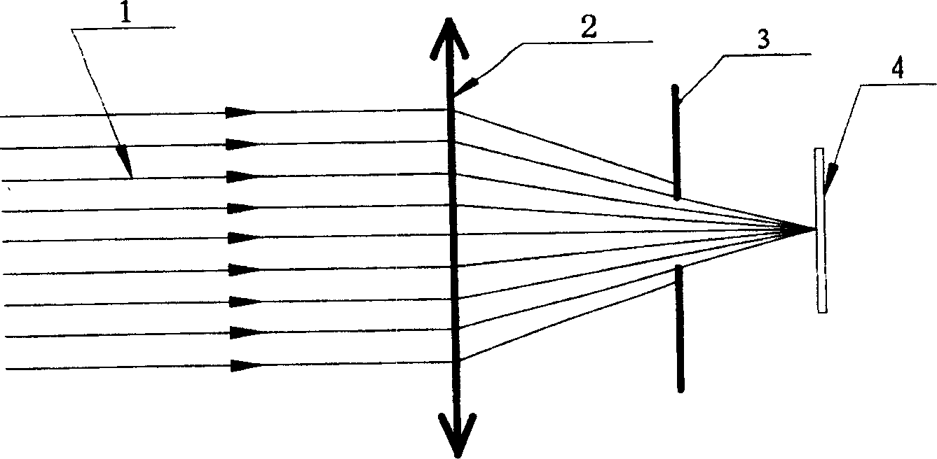
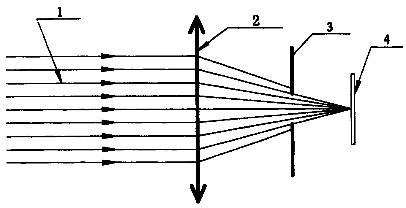
[0020] figure 1 The laser light 1 emitted by the medium carbon dioxide laser reaches the lens 2 through the optical path, and after focusing, it passes through the aperture 3 to the workpiece 4. Since the aperture on the aperture 3 is consistent with the shape of the spot to be engraved on the workpiece 4, the focused laser passes through the aperture After 3, the divergent light and unnecessary light are blocked, and the concentrated light consistent with the spot can reach the workpiece. In this way, the burn marks on the workpiece become smaller, that is, the aperture becomes smaller, and the method of the present invention can produce images far smaller than 100 micron microholes, preferably 30-100 micron round holes and / or micropits can be punched.

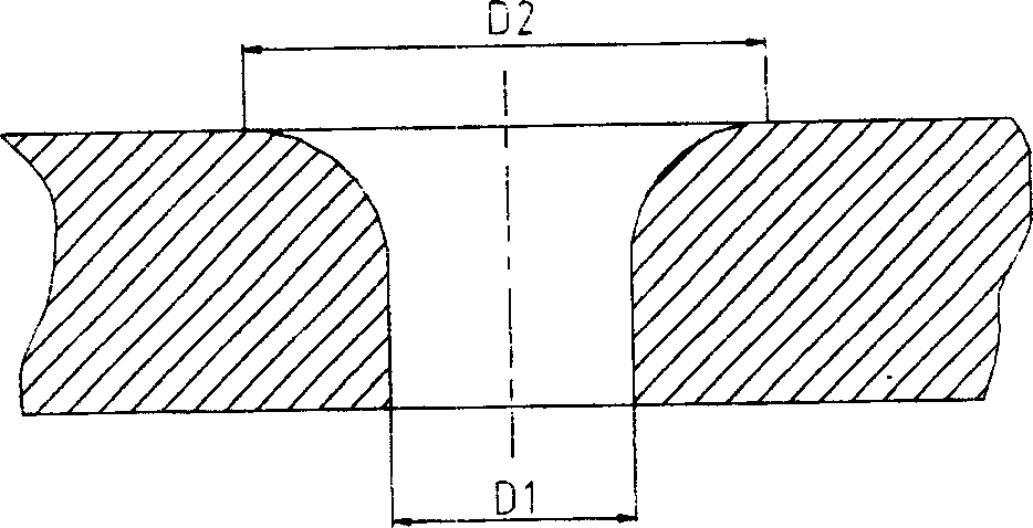
[0021] The microholes and / or micropits on the workpiece can be elliptical, the length of the long axis is 100-200 microns, and the length of the short axis is 30-80 microns. The microholes and / or micropits on the workpiece a...


PUM

PropertyMeasurementUnit
lengthaaaaaaaaaa
lengthaaaaaaaaaa
diameteraaaaaaaaaa

Abstract

The present invention belongs to a new laser microcarving method, in particular, it relates to a laser boring method. The laser emitted from laser source is passed through the lens, and can be acted on the workpiece to be carved. It is characterized by that between lens and workpiece a light diaphragm is set, and the form of aperture of the described light diaphragm is identical to the required and microcarved spot.

Description

Technical field: [0001] The invention relates to a microhole processing method, in particular to a laser micro-engraving method. Background technique: [0002] The laser beam has three characteristics: good directionality, high brightness, and large illuminance, which can be summed up in one point, that is, the energy of the laser beam is highly concentrated in space. For a highly parallel laser beam, it can be focused on a very small point after passing through the lens, and high temperature is generated at this point to melt or gasify the material, and the rapidly expanding shock wave penetrates the workpiece. This principle is widely used in industry for drilling and cutting. , welding and other processing, since the diameter of the focal spot after laser focusing is determined by the divergence angle of the laser used and the focal length of the objective lens, the diameter of the hole or micro-pit is limited by the diameter of the laser spot, so if you want to get a mic...

Claims


Application Information

Patent Timeline
Patent Type & Authority Patents(China)
IPC IPC(8): B23K26/36B23K26/382
Inventor 戴立盛赵越
Owner CHINA BANKNOTE PRINTING & MINTING
Why Eureka
Try Eureka