Image forming apparatus

A technology of image and loading part, which is applied in the direction of transportation and packaging, separation of objects, separation of piles, etc., can solve the problem of not being able to fully suppress the separation of the lifting plate and the pressure plate, and achieve the effect of suppressing high-frequency micro-sounds

Inactive Publication Date: 2016-12-07
BROTHER KOGYO KK
View PDF7 Cites 0 Cited by
  • Summary
  • Abstract
  • Description
  • Claims
  • Application Information

AI Technical Summary

Problems solved by technology

Therefore, when the reaction force from the paper feed roller (pickup roller) is received, the separation between th...

Method used


Image

  • Image forming apparatus
  • Image forming apparatus
  • Image forming apparatus

Examples


Embodiment Construction

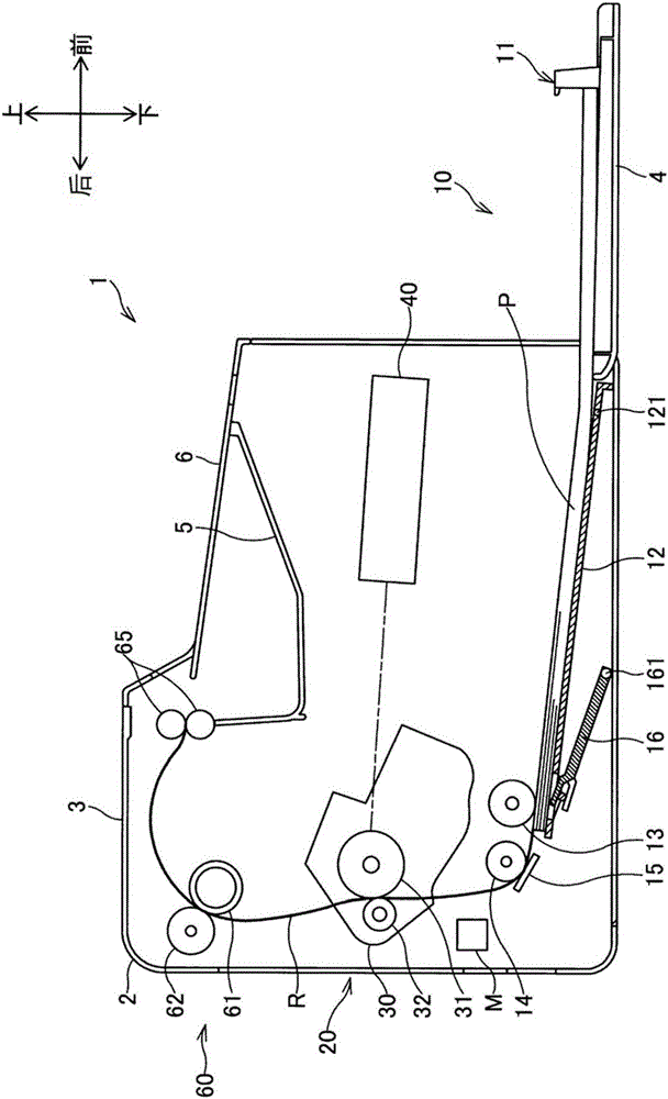
[0060] according to figure 1 The structure of the laser printer (hereinafter referred to as the printer) 1 of the present application will be described. In the following description, the directions are described based on the directions of a user using the printer 1 (an example of an “image forming apparatus”). which is, figure 1 Set the right side as "front", the left side as "rear", the near front side as "left", and the rear side as "right". Additionally, the figure 1 Let the upper side of , be "upper side" and the lower side be "lower side".

[0061]

[0062] Such as figure 1 As shown, the printer 1 has a substantially box-shaped main body housing 2 , a top cover 3 , and a front cover 4 , and houses a paper feeding unit 10 , an image forming unit 20 , and the like inside the main body housing 2 .

[0063] The top cover 3 is a cover covering the printer 1 from the rear end to the front end. The top cover 3 has an unillustrated rotation shaft at the rear, and is capab...


PUM


Abstract

Provided is an image forming apparatus capable of suppressing a high-frequency microphonic sound generated when a rising plate is repeatedly brought into contact with and away from a pressing plate when the sheet loaded on the press plate comes into contact with the sheet supply roller. The image forming apparatus includes a driving source, a moving member that moves in a vertical direction by a driving force transmitted from the driving source, a pressing plate that moves in association with movement of the moving member, and a sheet supply roller that is in contact with the sheet loaded by the pressing plate moved to the upper side; the pressing plate and the moving member are provided with a first restricting portion and a second regulating portion, wherein either the pressing plate or the moving member are provided with a restricting portion between the pressing plate and the moving member when any one of the pressing plate and the moving member moves upward and downward; the lower surface of the first regulating portion and the upper surface of the second regulating portion are brought into contact with the to-be-regulated portion in a state where the pressing plate is moved upward to a position where the sheet comes into contact with the sheet supply roller.

Description

technical field [0001] The present invention relates to an image forming apparatus, and more particularly, to an image forming apparatus including a paper feeding unit for feeding loaded sheets. Background technique [0002] Conventionally, there is an image forming apparatus (for example, Patent Document 1) that includes a platen on which sheets can be loaded, and is capable of conveying sheets one by one during image formation. One end portion of the pressure plate is rotatably fixed to the wall surface of the frame portion of the image forming apparatus via the rotating end. The ascending plate is fixed to the rotating shaft, and the inclination angle is changed according to the rotation of the rotating shaft. The end of the ascending plate abuts against the back of the pressing plate to lift the pressing plate, and when the ascending plate rotates, the contact position between the end of the ascending plate and the back of the pressing plate changes to change the inclin...

Claims


Application Information

Patent Timeline
IPC IPC(8): B65H1/14
CPCB65H1/14B65H2515/82
Inventor 冈本佳大山本浩洋
Owner BROTHER KOGYO KK
Why Eureka
Try Eureka