

Wire winding device
A wire coiling and coiling technology, which is used in transportation and packaging, transportation of filamentous materials, thin material processing, etc., can solve the problems of uneven wire sticking, inability to achieve automatic winding, wire damage, etc., and achieve liberation. Manpower, high degree of cooperation, and the effect of improving production efficiency
- Summary
- Abstract
- Description
- Claims
- Application Information
AI Technical Summary
Problems solved by technology
Method used
Image

Examples
Embodiment Construction
[0020] The specific embodiment of the present invention will be further described below in conjunction with accompanying drawing:
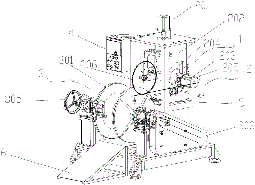
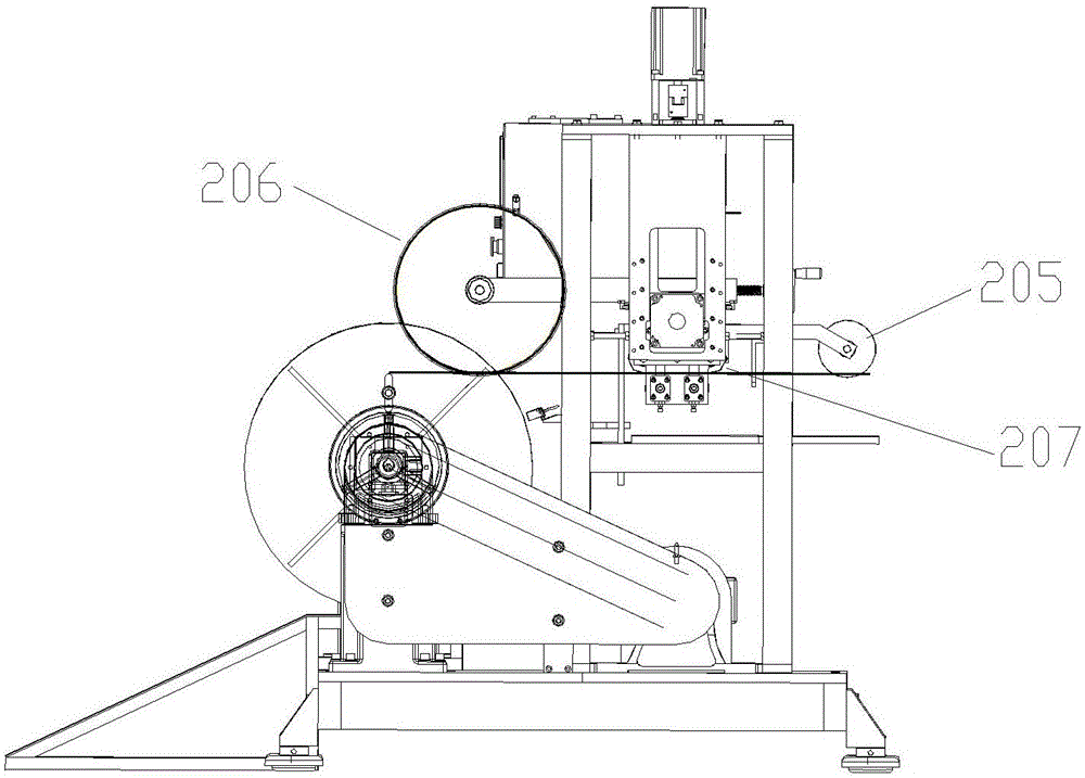
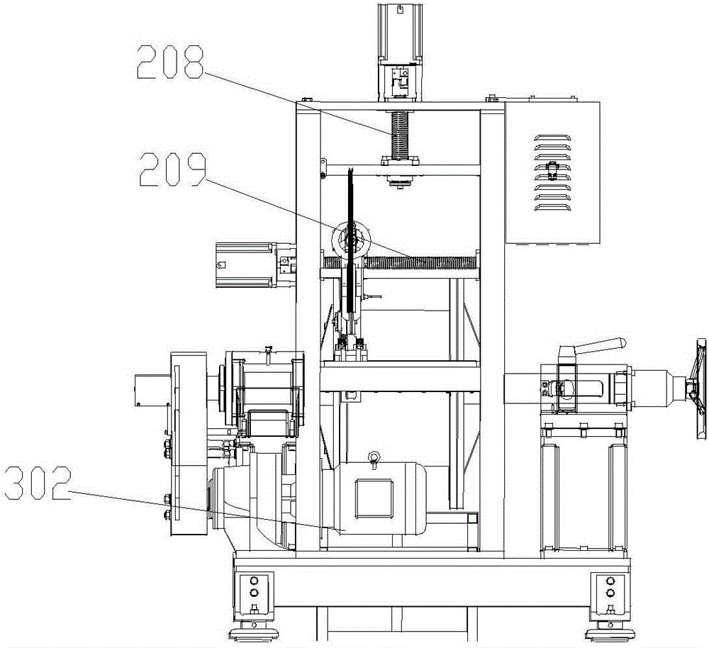
[0021] like Figure 1-3 As shown, the wire winding device includes a frame 1, a controller 4, a wire mechanism 2 and a winding mechanism 3, the controller 4, the wire mechanism 2 and the winding mechanism 3 are installed on the frame 1, and the winding mechanism 3 is set Downstream of the lead mechanism 2, the lead mechanism 2 includes a first motor 201, a second motor 203, a first screw 208, a second screw 209, a first support 202, a second support 204 and a set of guide wheels, and the first motor 201 is installed on The top of the frame 1 is connected with the first screw rod 208, the first support 202 is screwed on the first screw rod 208 and moves vertically along the first screw rod 208, the second motor 203 is installed on the side of the first support 202, and The second screw rod 209 is connected, the second support 204 is screwed on the...
PUM
 Abstract
Description
Claims
Application Information