Electrode sensor assembly for electroretinography and pattern electroretinography

a technology of electroretinography and electroretinography, applied in the field of electroretinography and pattern electroretinography, to achieve the effect of improving patient comfort and cooperation

Active Publication Date: 2014-05-22
DIOPSYS INC
View PDF3 Cites 9 Cited by
  • Summary
  • Abstract
  • Description
  • Claims
  • Application Information

AI Technical Summary

Benefits of technology

[0021]It will be understood that the data collected is analyzed in the standard manner, but the collection of such data as well as patient comfort and cooperation is improved.

Problems solved by technology

Many prior art electrodes are used and reused, which is undesirable.

Method used


Image

  • Electrode sensor assembly for electroretinography and pattern electroretinography
  • Electrode sensor assembly for electroretinography and pattern electroretinography
  • Electrode sensor assembly for electroretinography and pattern electroretinography

Examples


Embodiment Construction

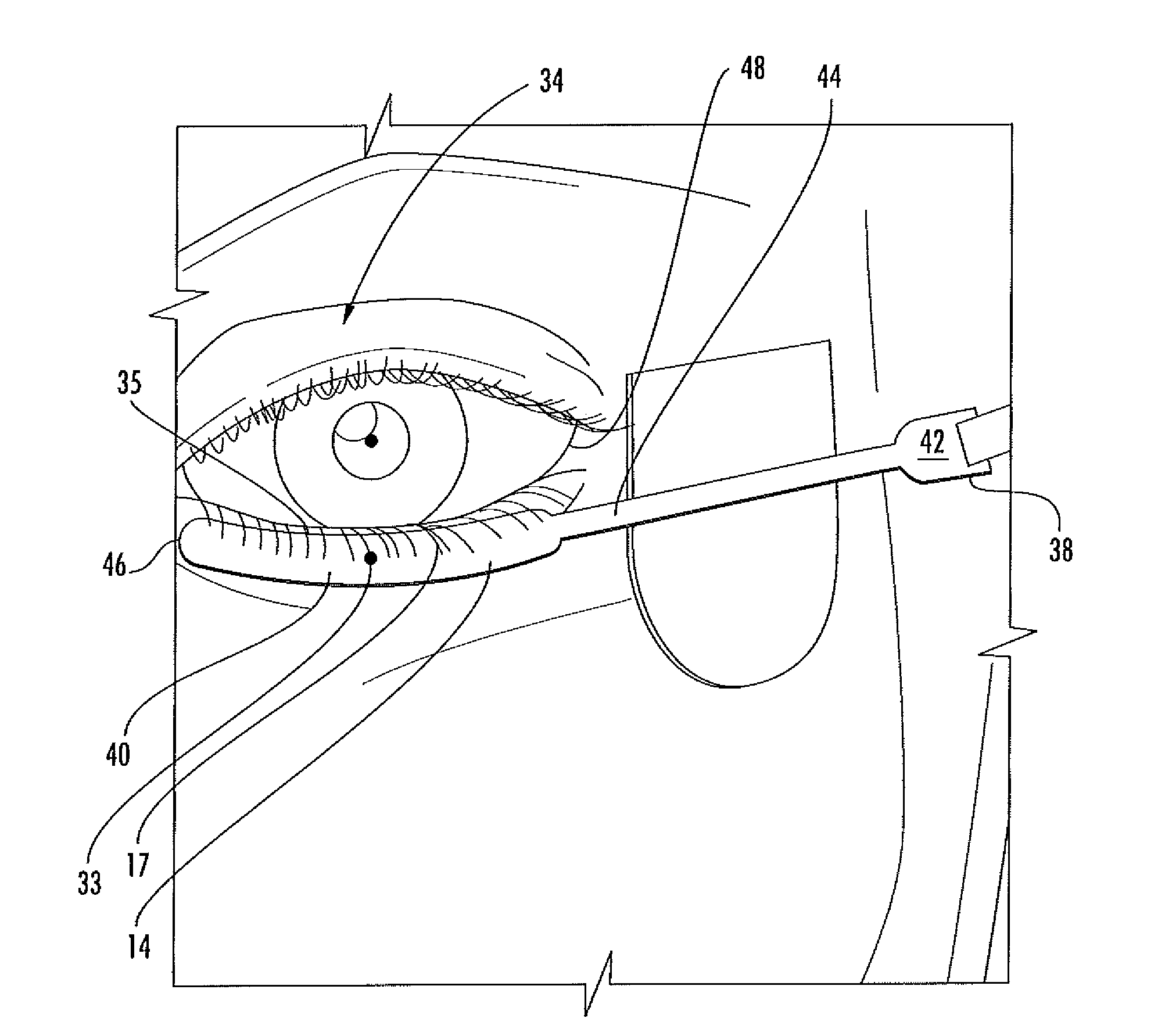
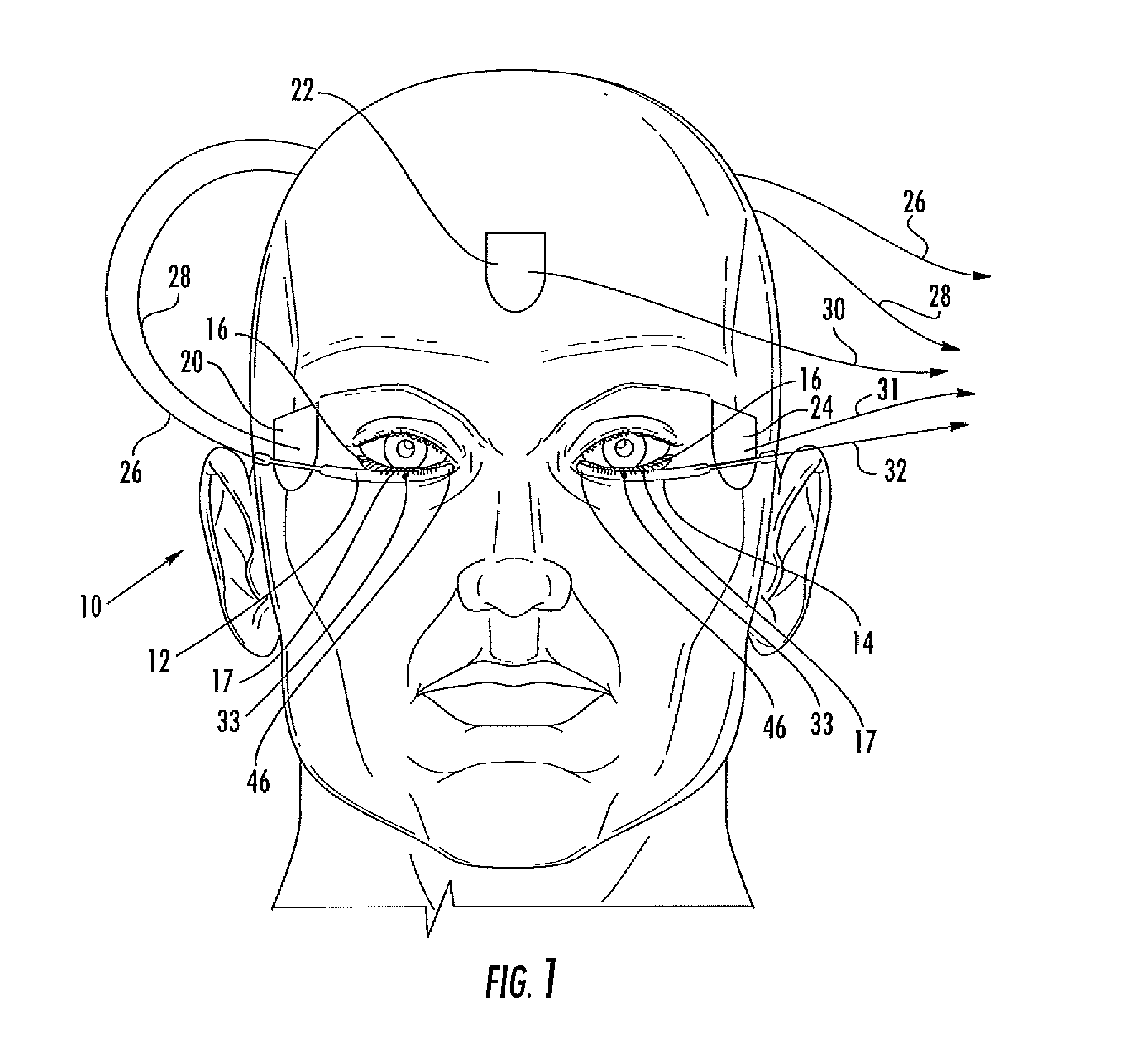
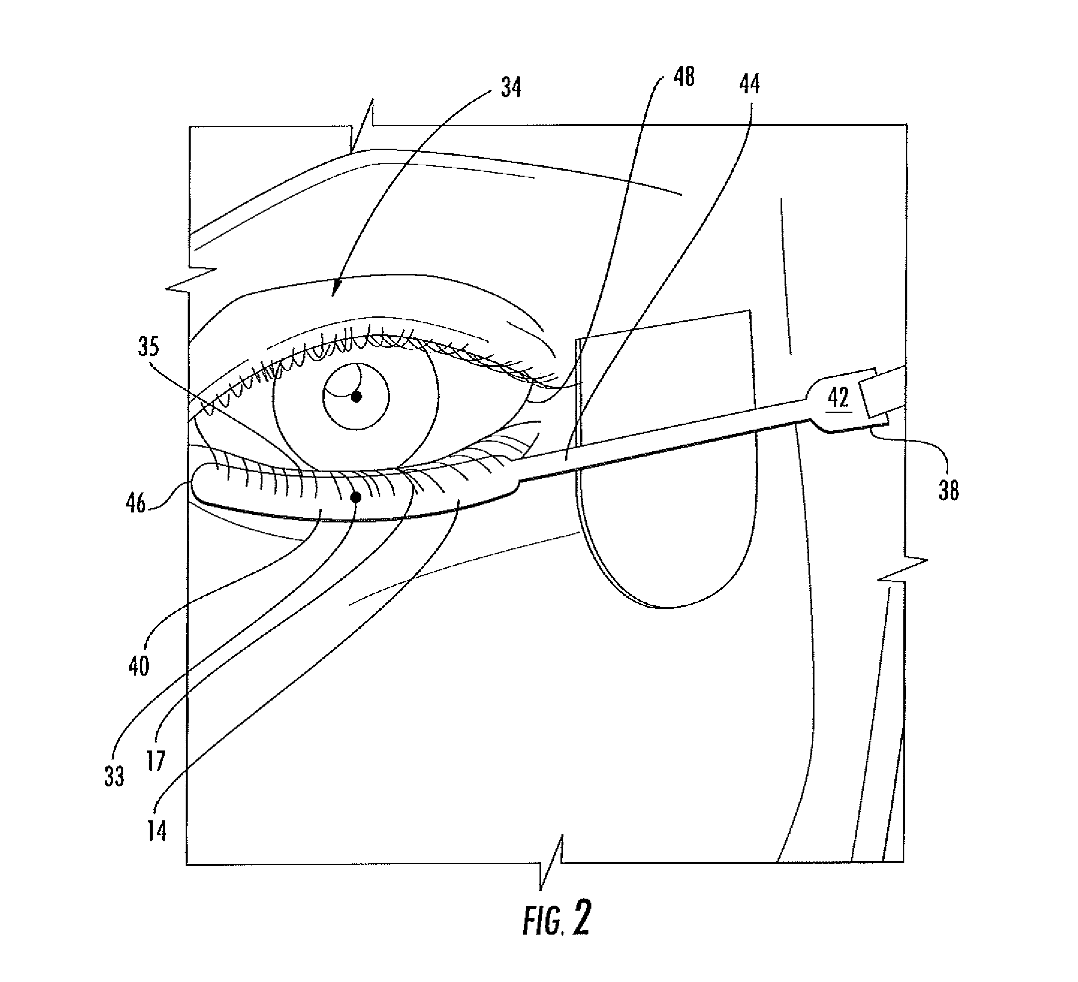
[0026]FIG. 1 is a front plan view of the front of a face 10 showing sensors 12 and 14, which are the sensors used for pERG or ERG set up and testing. The present invention is directed to the right and left lower lid sensors 12 and 14, respectively, which are elongated and thin, placed on the skin (no number) on the lower eyelid 16, with lower eyelashes 17 covering the sensors to pick up retinal signals. The signals from the lid sensors 12 and 14 are utilized in conjunction with signals in OD Reference, Ground and OS Reference sensors, 20, 22 and 24, respectively, with sensors 20 and either side of the temple and sensor 22 located centrally above the eyebrows.

[0027]With suitable pERG testing, signals are generated at the lid sensors 12 and 14. Reference sensors are placed in an area that is distant from any response generated by the retina. The references serve as controls for the pERG test. The generated signals from the procedure are carried on conductors 26 for OD lid sensor 12, 2...


PUM


Abstract

A multilayer electrode sensor assembly for electroretinography and pattern electroretinography formed as a thin strip to fit under a lower eyelid and contain an electrode in line with the pupil of an eye with signals detected carried through an integrally formed thin conductive strip to a terminal to be connected to an electrical conductor for carrying such signals to an analyzer.

Description

BACKGROUND OF THE INVENTION[0001]This invention relates to an electrode sensor assembly for electroretinography and pattern electroretinography.[0002]Determining the functioning of the retina is significant in diagnosing, assessing and monitoring the progression of dysfunction due to disease or trauma. Electroretinography (ERG) and Pattern Electroretinography (pERG) are systems which use different visual stimuli including patterns to stimulate the eye and causes the retina to generate responses, and resulting signals are analyzed. An analysis of signal amplitude and latency leads to monitoring and diagnosis of retinal health.[0003]Microelectrical signals are generated in the retina during ERG and pERG testing and are analyzed by standard diagnostic equipment and techniques. pERG vision testing is a well established technology with a broad foundation of scientific support. This invention permits significantly improved test administration.[0004]A significant aspect of such systems is ...

Claims


Application Information

Patent Timeline
Patent Type & Authority Applications(United States)
IPC IPC(8): A61B5/0496
CPCA61B5/0496A61B2562/0209A61B2562/0215A61B5/398
Inventor GARCIA, ALBERTO GONZALEZLEPONE, DONALD E.
Owner DIOPSYS INC
Why Eureka
Try Eureka