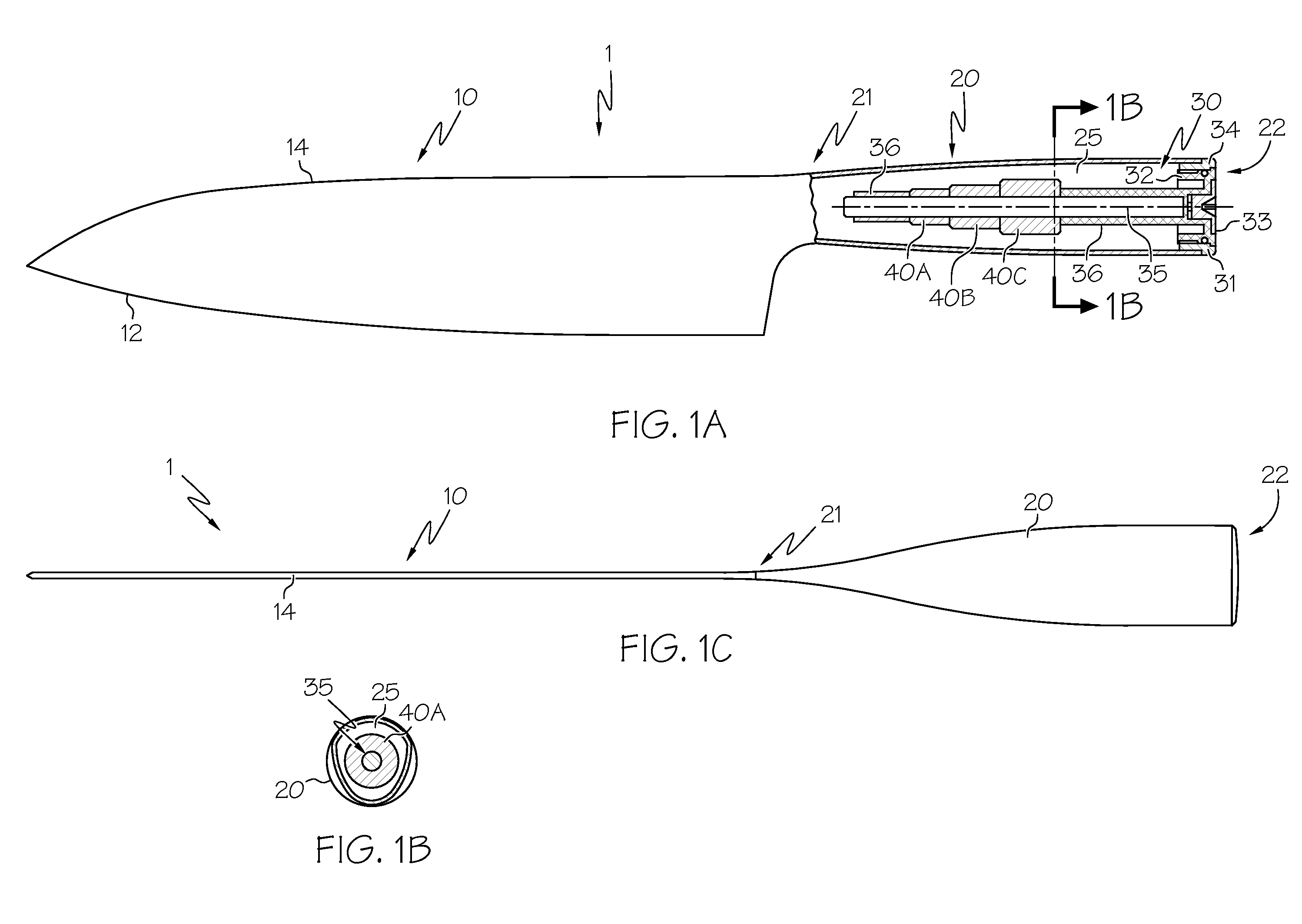
[0004]These desires are met by the present invention, where a kitchen knife capable of easy user-defined balancing is disclosed. With this preferred arrangement, the overall weight balance of the knife can be optimized, thereby reducing the onset of user fatigue. Such is especially valuable in commercial kitchen applications, where a user may be working with the knife for hours at a time.
[0005]According to a first aspect of the invention, a kitchen knife includes a
metal blade, a handle with a hollow compartment, one or more removable weights and a weight mounting
assembly that cooperates with the handle to allow the weights to be secured within the hollow compartment. The blade includes a sharp
cutting edge and a blunted edge opposite the cutting edge. The handle is connected to the blade, while the weight mounting
assembly can engage the handle at an end of the handle that is substantially opposite of the end of the handle nearest the blade. In this way, once a user has placed the weight or weights into a desired axial location within the hollow compartment, the weight mounting assembly can effect an axially balanced configuration suitable to the user's particular needs.
[0006]Optionally, the blade can be made from a suitable cutting material, such as a
high carbon or otherwise alloyed steel. Similarly, a material making up the handle can be the same material, or can be a stainless steel. The one or more weights may be disposed in the hollow compartment such that balanced knife configuration occurs mainly along a substantially lengthwise direction of the handle. In one form, the handle engages the weight mounting assembly through a permanent connection, for example,
welding a ring or related
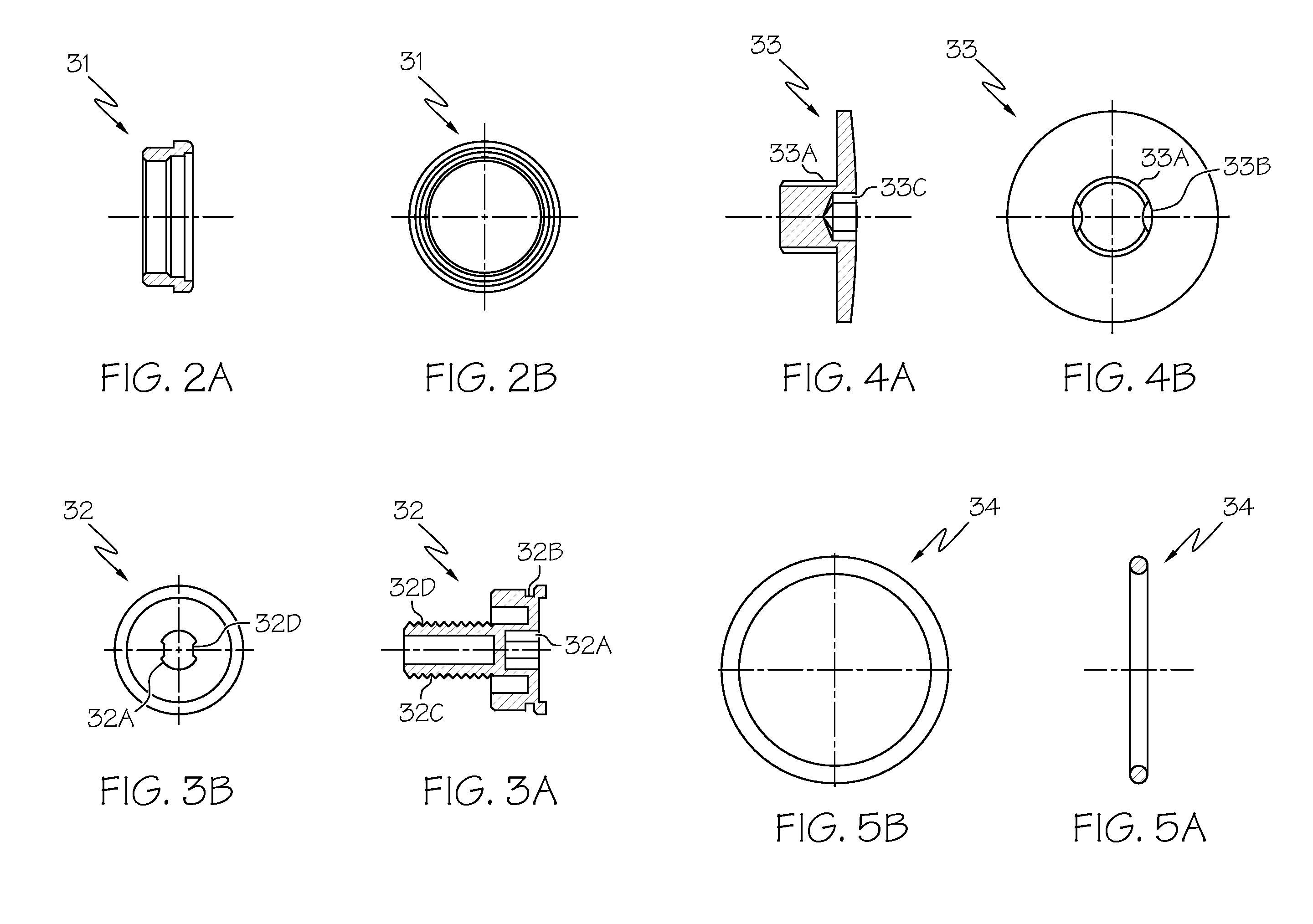
mount to the handle. In addition, the one or more weights may be, in situations where multiple weights are used, axially disposed relative to one another within the hollow compartment. The weight mounting assembly may be formed from numerous components, including a stopper or related main structural member that threadably or otherwise engages the ring or related
mount that (through the aforementioned
welding) is directly and permanently affixed to one or both of inner and rear surfaces of the handle, and an end cap or cover that is attached to the stopper. The stopper functions as an anchor for a generally axial rod, post or screw upon which the weight or weights (which could have complementary threaded bores formed through them) can be secured in a preferred axial place. The cover can be used to substantially close off the remaining components from the ambient environment once the weight mounting assembly is placed within the handle, and may be attached to the stopper in such a way that
insertion or removal of the end cap (by screwing or unscrewing) of it produces sympathetic movement in the stopper which, by virtue of its threaded relationship with the ring or similar
mount, can be inserted or removed by the screwing or unscrewing motion. Preferably, movement of the stopper and end cap is rotational, so that such rotational movement in one produces comparable rotational movement in the other. In addition, one or more indexing devices can be placed on the rod to cooperate with it to keep the weights disposed on the rod in a fixed axial location thereon. The weight mounting assembly allows relatively precise placement of the weight or weights in accordance with a preferred balance, heft or related feel as desired by the user. In another option, the handle may include protuberances on the outer surface thereof to promote improved user grip. Such construction is beneficial in avoiding having the knife slip in the user's hand.
[0007]According to another aspect of the invention, a kitchen knife including a
metal blade with a cutting edge, a handle integrally defining an axially elongate hollow compartment and one or more removable weights disposable in the hollow compartment is disclosed. The cooperation between the weight and the hollow compartment is such that upon placement of the weight in the hollow compartment, a predetermined balance characteristic of the knife can be established. By being integrally constructed, the handle and the blade define a single, one-piece (i.e., unitary) structure, rather than being fastened or adhesively glued together. Such unitary construction, which may be achieved by forming the handle and blade from a single piece of material, or by
welding the two together along with post-weld
machining, is not only more structurally robust, but also minimizes gaps or like locations on the outer surface of the knife that can provide a breeding ground for
bacteria or other contaminants.
[0008]The handle includes a proximal end and a distal end such that in a preferred embodiment, the hollow compartment terminates at the proximal end and the blade joins the handle at the distal end. The knife may further include a weight mounting assembly configured in a manner generally similar to that discussed above in conjunction with the previous aspect. Closure of the proximal end of the handle occurs with the end cap, which (in a manner similar to that discussed above) when in place closes off access to the hollow compartment that terminates at the proximal end of the handle. As previously stated, a stopper may be threaded so that it engages the handle as a device that can be screwed on or off by movement imparted to it through the end cap. In addition, a rod may be axially disposed within the hollow compartment. The rod may further be in the form of a tube, post or screw and aligned along the handle's axial dimension. To enhance cooperation between the weights and the rod, the weights may have a substantially axial bore formed through them such that they can engage the rod through the substantially axial bore. Connection between the bore and rod may be through slip fit, friction fit or threaded relationship, the latter where complementary threads promote a nut-and-bolt like fit between them. In a slip fit configuration, the weights may be held in a preferred axial place by protrusions on the rod, or by sleeves (for example, tight-fitting rubber tubes) that can fit on the outer surface of the rod and remain in place by frictional contact,
adhesive or other fastening or other means. Threaded cooperation between various components such as the stopper and a complementary surface on the handle (or a stopper-engaging mount, such as a ring, affixed to the surface of the handle) is such that
ease of access to the hollow compartment through unscrewing the stopper is promoted. Likewise, screwing the stopper into the complementary threads on the mount or handle makes it easy to put the knife back together again once the desired weight balance is established.


