Foldable deceleration strip
A technology of deceleration belts and deceleration motors, which is applied to roads, road signs, traffic signals, etc., and can solve the problems of high-speed and barrier-free passage of vehicles that cannot be folded
- Summary
- Abstract
- Description
- Claims
- Application Information
AI Technical Summary
Problems solved by technology
Method used
Image

Examples
Embodiment Construction
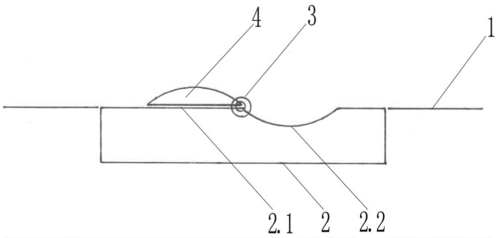
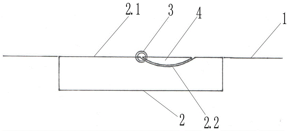
[0009] exist figure 1 , figure 2 Among them, the present invention provides a folding deceleration belt, which includes a lower embedded base flush with the road, a strip-shaped deceleration belt and a driving motor, and is characterized in that: the base of the folding deceleration belt is a rectangular parallelepiped base (2), and the rectangular parallelepiped One side of the center line of the base (2) is a plane (2.1), and the other side is an arc-shaped groove (2.2). A bearing seat is fixed at both ends of the center of the cuboid base (2). Connected between the shafts is the arc corner tip of the arc-shaped long speed reduction belt complementary to the arc-shaped concave long groove. One end of the shaft is driven by a stepping reduction motor. When the speed reduction belt is not required, the stepping The forward rotation of the reduction motor drives the arc-shaped long strip speed reduction belt to rotate 180°, so that the arc-shaped long strip speed bump (4) is ...
PUM
 Abstract
Description
Claims
Application Information
PatSnap Eureka turns technology decisions into work you can execute. Powered by our Innovation Knowledge Graph, it runs expert workflows across engineering, life sciences, materials and intellectual property. Get your review-ready output in minutes.


