Leakage plugging device for dams

A technology of dams and tarps, applied in water conservancy projects, marine engineering, construction, etc., can solve problems such as major safety hazards and low leakage plugging efficiency

Active Publication Date: 2018-01-02
田生
View PDF5 Cites 0 Cited by
  • Summary
  • Abstract
  • Description
  • Claims
  • Application Information

AI Technical Summary

Problems solved by technology

Whether it is the first method or the second method, there are relatively large safety hazards, and the efficiency of plugging is also relatively low.

Method used


Image

  • Leakage plugging device for dams
  • Leakage plugging device for dams
  • Leakage plugging device for dams

Examples


Embodiment Construction

[0032] Specific embodiments of the present invention will be described in detail below in conjunction with the accompanying drawings. It should be understood that the specific embodiments described here are only used to illustrate and explain the present invention, and are not intended to limit the present invention.

[0033] In the present invention, in the absence of a contrary statement, the orientation words included in the term, such as "upper, lower, inner, outer, top, bottom", etc., only represent the orientation of the term in the normal use state, or for the purpose of A common term understood by those skilled in the art, and should not be considered as a limitation of the term.

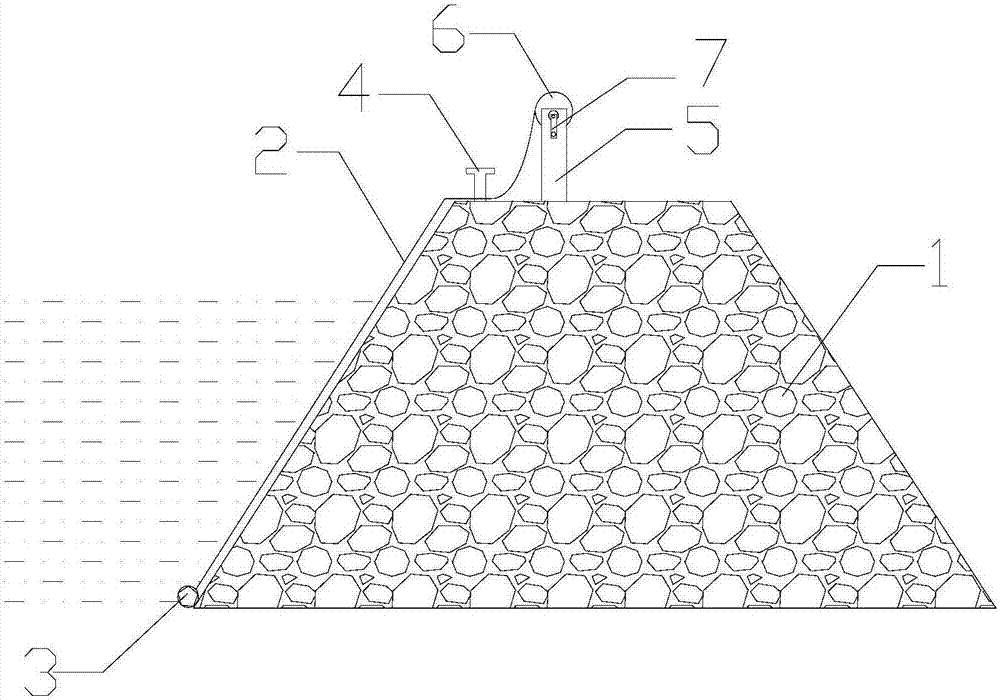
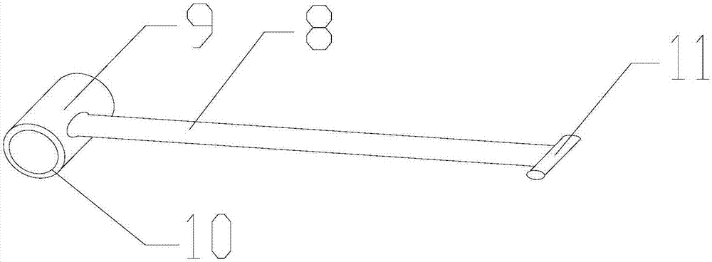
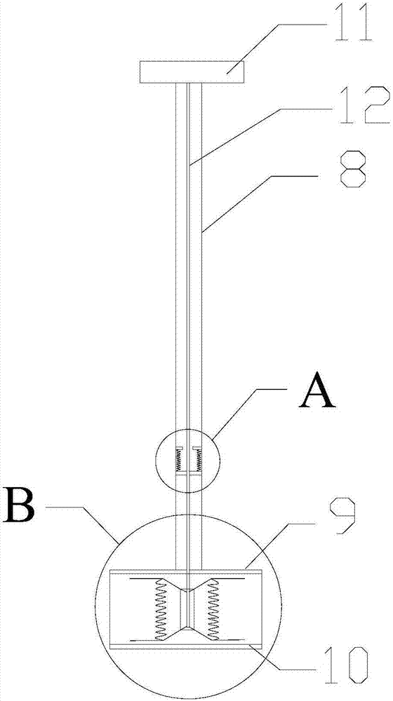
[0034] The invention provides a dam leak plugging device, such as figure 1 and figure 2 As shown, it includes waterproof cloth 2, counterweight 3 and propulsion mechanism; The surface water slope of the embankment 1 moves downward; the two sides of the waterproof cloth 2 along the length...


PUM


Abstract

The invention discloses a dam leakage stopping device which comprises waterproof cloth, a counterweight and a propulsive mechanism; the counterweight is arranged at one end of the waterproof cloth in the length direction; the propulsive mechanism can be matched with the counterweight to propel the counterweight to move downwards along the water facing slope of a dam; fixing holes are formed in the two sides of the waterproof cloth in the length direction; and fixing piles can be installed in the fixing holes to fix the other end, in the length direction, of the waterproof cloth to the top of the dam. The dam leakage stopping device can safely and efficiently block seepage points of the dam in a flood season.

Description

technical field [0001] The invention relates to a flood control device, in particular to a leakage plugging device for a dam. Background technique [0002] Leakage often occurs in dikes and dams during the flood season. Once there is leakage in the dam, flood control personnel generally need to adopt two methods to solve it: the first is to manually launch the flood control personnel to find the exact leakage point, and then fill the leakage point with sediment to protect the dam The second method is that the flood control personnel first estimate the approximate location of the leak point, and then artificially launch water and lay a waterproof cloth near the leak point to block the leak point, so as to achieve the purpose of repairing the leak. Whether it is the first method or the second method, there is a greater potential safety hazard, and the efficiency of plugging is also relatively low. Contents of the invention [0003] The object of the present invention is to...

Claims


Application Information

Patent Timeline
Patent Type & Authority Patents(China)
IPC IPC(8): E02B3/16
CPCE02B3/16
Inventor 田生
Owner 田生
Why Eureka
Try Eureka