Hydraulic reciprocating seal dynamic property detection device and design

A technology of dynamic performance and monitoring device, which is applied in the direction of fluid pressure actuation device, fluid pressure actuation system test, mechanical equipment, etc., can solve the problem of dynamic performance detection of hydraulic reciprocating seal, etc., and achieve the effect of ensuring accuracy

Active Publication Date: 2016-12-07
WUHAN UNIV OF TECH
View PDF7 Cites 23 Cited by
  • Summary
  • Abstract
  • Description
  • Claims
  • Application Information

AI Technical Summary

Benefits of technology

This new design allows for better testing of both the pumping rods used by an Hydrolumatic Actuators (HA) system and its bearings that are subjected to high pressures while still being able to work properly. It also includes fused methods to accurately detect changes caused by these movements over time.

Problems solved by technology

This patented technical solution describes a new type of hydrocycling sealed device used in hydropulsive power systems called hydrocracking machines or refrigeration compressor systems. These systems use different ways to monitor the behavior of their components - including the movement of the valve stem within the machine's housing, the presence of lubricant residue inside the closed chamber where the hydrous liquid works together, and changes made overtime caused by factors like temperature fluctuations. Additionally, there exist challenged issues such as unstable flow rates and excessive wear debris accumulation when utilizing these techniques alone.

Method used


Image

  • Hydraulic reciprocating seal dynamic property detection device and design
  • Hydraulic reciprocating seal dynamic property detection device and design
  • Hydraulic reciprocating seal dynamic property detection device and design

Examples


Embodiment 1

[0037] Example 1. Hydraulic reciprocating seal dynamic performance monitoring device

[0038] The device can detect the dynamic performance of the hydraulic reciprocating seal without changing the normal operating state of the hydraulic actuator, and can realize the hydraulic reciprocating seal contact strain signal, fluid pressure signal, oil leakage and The collection of tension pressure signal and displacement signal during the movement of the actuator, through the method of multi-sensing information fusion, realizes the friction and leakage performance detection of hydraulic reciprocating seals, and provides a basis for improving the reliability of hydraulic reciprocating seals.

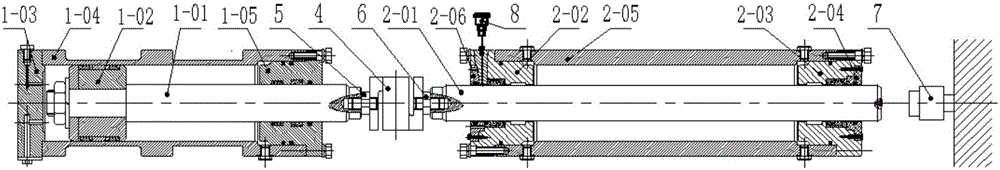
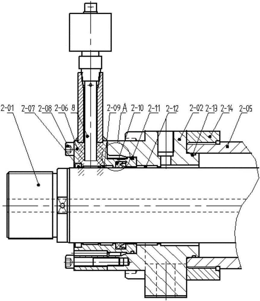
[0039] The structure of the device is as Figure 1 to Figure 9 As shown, according to the detection content, it is divided into two modules, the dynamic friction performance detection module and the leakage performance detection module.

[0040] The dynamic friction performance detection module ...

Embodiment 2

[0045] Embodiment 2. Design of hydraulic reciprocating seal dynamic performance monitoring device

[0046] The dynamic performance monitoring device of the hydraulic reciprocating seal is designed according to the following method. The design of the device is divided into the design of the dynamic friction performance detection module and the leakage performance detection module.

[0047] 1. Piston rod seal dynamic friction performance detection module:

[0048] (1) Structural design of the dynamic friction performance detection module of the piston rod seal:

[0049] In order to accurately measure the frictional force of the piston rod seal, the first test cylinder 2 is in the form of a double-acting cylinder. Since the material of the piston rod seal is one of the variable parameters of the test, in order to facilitate the disassembly of the seal, the piston rod seal is installed on the gland. Every time the piston rod seal is disassembled, only the gland on the cylinder he...


PUM


Abstract

The invention provides a hydraulic reciprocating seal dynamic property detection device and design. The device comprises a dynamic friction property detection module, an inner leakage detection module and an outer leakage detection module which share a part of a testing device. When a hydraulic cylinder (1) is connected with a first testing cylinder (2) through an S-shaped tension pressure sensor (4), the S-shaped tension pressure sensor only achieves a connection effect, and thus the structure of the outer leakage detection module and the structure of the dynamic friction property detection module are similar. As long as an oil level sensor (8) is additionally arranged on a left gland of the first testing cylinder, the oil level sensor is welded to the left gland of the first testing cylinder through a supporting steel tube. According to the detection device, under the premise that the function requirements of a hydraulic reciprocating structure and a hydraulic execution element are not changed, detection of the dynamic friction property and the leakage property of a hydraulic reciprocating seal in application is conducted according to the normal operation condition of the hydraulic execution element. According to the hydraulic reciprocating seal dynamic property detection device and design, analysis and evaluation of the dynamic property of the hydraulic reciprocating seal can be achieved.

Description


Claims


Application Information

Patent Timeline
Owner WUHAN UNIV OF TECH
Why Eureka
Try Eureka