Circulating fluidized-bed boiler with multiple separators and annular hearth

A circulating fluidized bed and cyclone separator technology, which is applied to fluidized bed combustion equipment, fuel burning in a molten state, lighting and heating equipment, etc. The layout plan cannot be applied to the circulating fluidized bed boiler, etc.

Active Publication Date: 2016-12-07
INST OF ENGINEERING THERMOPHYSICS - CHINESE ACAD OF SCI
View PDF6 Cites 6 Cited by
  • Summary
  • Abstract
  • Description
  • Claims
  • Application Information

AI Technical Summary

Problems solved by technology

However, due to the existence of the water-cooling column, the distribution of the gas-solid flow field in the furnace is changed, especially for the two separators located in the middle of both sides of the furnace. Gas-solid circulation between vessels is weakened
The multi-separator layout plan summarized in the development of the circulating fluidized bed boiler with a rectangular upper section of the furnace is no longer applicable to the circulating fluidized bed boiler with this structure

Method used


Image

  • Circulating fluidized-bed boiler with multiple separators and annular hearth
  • Circulating fluidized-bed boiler with multiple separators and annular hearth
  • Circulating fluidized-bed boiler with multiple separators and annular hearth

Examples


Embodiment Construction

[0031] The technical solutions of the present invention will be further specifically described below through the embodiments and in conjunction with the accompanying drawings. In the specification, the same or similar reference numerals designate the same or similar components. The following description of the embodiments of the present invention with reference to the accompanying drawings is intended to explain the general inventive concept of the present invention, but should not be construed as a limitation of the present invention.

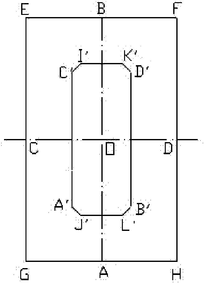
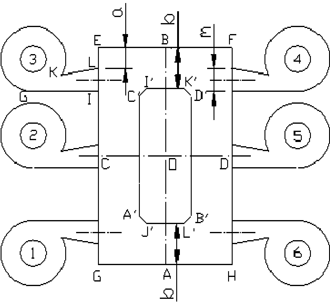
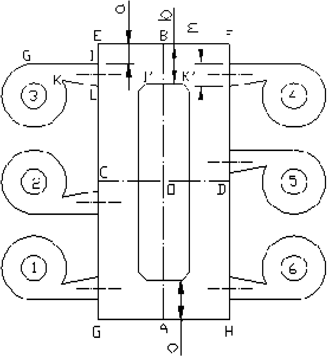
[0032] The annular furnace circulating fluidized bed boiler with multiple separators of the present invention includes a furnace with an annular cross section and a plurality of parallel cyclone separators; each cyclone separator is composed of an inlet flue and a cylinder; each cyclone separates The cylinder structure and size of the device are the same.

[0033] Specifically, the furnace with a ring-shaped cross section has a water cooling ...


PUM


Abstract

A circulating fluidized-bed boiler with an annular hearth comprises the hearth and two sets of cyclone separators. The cyclone separators are correspondingly arranged on the outer sides of the two side walls. Each set of cyclone separators is provided with three cyclone separators, and all the cyclone separators are the same in cylinder structure and size. In the plane crossing all the hearth smoke outlet center points, the hearth smoke outlet center points of the two separators on the outmost side in one set of separators and the hearth smoke outlet center holes of the two separators on the outermost side in the other set of separators are symmetric about the intersecting point of the hearth center face perpendicular to the first side wall and the hearth center face perpendicular to the second side wall; and the hearth smoke outlet center points of the two separators on the outmost side in each set of cyclone separators are axially symmetric about the hearth center line formed by the intersecting line of the hearth center face perpendicular to the first side wall and the plane. The position relation of the two cyclone separators on the outmost side in each set of cyclone separators meets the conditions that when b is smaller than or equal to 2m, a is larger than or equal to b / 3 and smaller than b-0.3m; and when b is larger than 2m, a is larger than or equal to m / 2 and smaller than b-0.3m.

Description

technical field [0001] The invention relates to the technical field of circulating fluidized bed boilers, in particular to the arrangement of cyclone separators of circulating fluidized bed boilers. Background technique [0002] Since the circulating fluidized bed combustion technology was applied in the field of power generation, it has been developing in the direction of large capacity and high parameters. While the capacity and parameters of the circulating fluidized bed boiler are enlarged, in order to ensure the separation efficiency, the size of the cyclone separator cannot be increased synchronously with the size of the furnace, so the parallel arrangement of multiple cyclone separators is a commonly used structure for large circulating fluidized bed boilers form. However, the gas-solid two-phase flow in a circulating fluidized bed with multi-cyclone separators belongs to the problem of multiphase flow in parallel channels. Both the literature reports and the actual ...

Claims


Application Information

Patent Timeline
Patent Type & Authority Applications(China)
IPC IPC(8): F23C10/08
Inventor 王小芳孙运凯吕清刚那永洁高鸣
Owner INST OF ENGINEERING THERMOPHYSICS - CHINESE ACAD OF SCI
Why Eureka
Try Eureka