Efficient cyclone separation device for dust remover

The technology of a cyclone separation device and a vacuum cleaner, which is applied to the suction filter and other directions, can solve the problems that the small particle dust is not easily separated, the separation efficiency is reduced, and the system resistance is high, and the effect of improving the suction force, reducing the capacity loss and improving the suction power

Inactive Publication Date: 2013-07-03
NANJING LG PANDA APPLIANCES
View PDF5 Cites 34 Cited by
  • Summary
  • Abstract
  • Description
  • Claims
  • Application Information

AI Technical Summary

Problems solved by technology

[0009] However, the cyclone separation device as described above has the following problems: after the air enters the cyclone separation device from the air inlet, the structure in the elliptical barrel makes the airflow velocity gradually decrease, and when the air flows from the long axis end to the short axis end, it will flow from the outside to the short axis end. The vortex is directly transferred to the inner vortex, the separation efficiency is reduced, and the small particles of dust are not easy to separate; the loss caused by the air flow to the inner vortex in this structure is large, and the system resistance is high

Method used


Image

  • Efficient cyclone separation device for dust remover
  • Efficient cyclone separation device for dust remover
  • Efficient cyclone separation device for dust remover

Examples


Embodiment Construction

[0034] The present invention will be described in detail below with reference to the drawings and examples. The same symbols are used for the same components in the present invention as in the prior art.

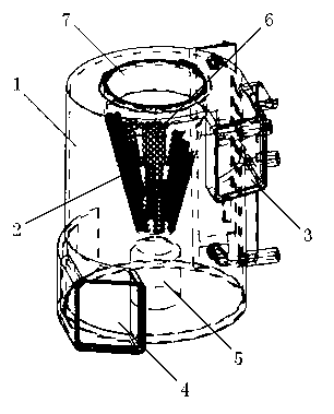
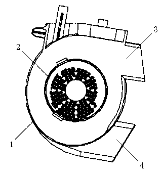
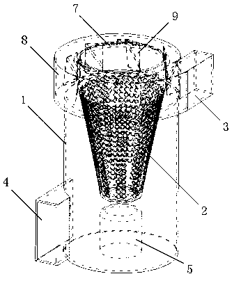
[0035] image 3 It is a perspective view of the vacuum cleaner cyclone separation device of the present invention. Such as image 3 As shown, the high-efficiency cyclone separation device for a vacuum cleaner of the present invention includes a barrel body 1 and a filter 2 disposed inside the barrel body with openings at both ends. The filter 2 has a large opening at the upper end and a small opening at the lower end, and the whole body is covered with filter holes 6 . An air inlet 3 communicating with the barrel is formed on one side of the upper end of the barrel body 1 along the tangential direction of the outer wall, and a dust removal port 4 of the barrel body 1 communicating with the barrel is formed in the tangential direction of the lower outer wall on the side op...


PUM


Abstract

The invention discloses an efficient cyclone separation device for a dust remover, which comprises a barrel body and a filter arranged inside the barrel body, wherein an air inlet communicated with the inside of the barrel is formed on one side of the upper end of the barrel body in tangential direction of the outer wall; the cross section of the outer wall of an air intake way at the upper end of the barrel body, communicated with the air inlet, is helical; and a plurality of air intake guide vanes are evenly arranged inside the air intake way in the circular direction. According to the efficient cyclone separation device for the dust remover, the cross sectional area is gradually reduced from the air inlet to the inside to facilitate the increasement of the tangential speed of the airflow inside the air intake way along with the reduction of the cross sectional area, so as to increase the separation efficiency of an outer eddy side; the air intake guide vanes are arranged inside the air intake way and evenly distributed in the circular direction to facilitate the conversion of the axial speed of the airflow to the tangential speed, reduce the loss of energy of axial downwards speed of an inner eddy and improve the suction power of the dust remover; and therefore, the efficient cyclone separation device for dust remover has the advantages of high efficiency and less power loss and can effectively improve the suction power of a dust remover motor.

Description

technical field [0001] The invention belongs to the field of vacuum cleaners, in particular to a high-efficiency cyclone separation device for vacuum cleaners. Background technique [0002] Vacuum suction is a cleaning and sanitary appliance used to remove dust from floors, carpets, walls, furniture, clothing and various gaps. Vacuum cleaners generally include a vacuum cleaner motor that generates suction from an imported power supply, a motor inlet that forms an air path system, a suction nozzle, a hose, and a dust collection device that collects inhaled matter. [0003] According to the shape of vacuum cleaners, they can be divided into upright vacuum cleaners, horizontal vacuum cleaners and portable vacuum cleaners. [0004] Generally speaking, the upright vacuum cleaner includes a front cover, a rear cover and a bottom case. There is a vacuum hose connection device on the top of the front cover, a horizontal wire reel and a dust collection bucket for collecting suction...

Claims


Application Information

Patent Timeline
Patent Type & Authority Applications(China)
IPC IPC(8): A47L9/16
Inventor 王柳
Owner NANJING LG PANDA APPLIANCES
Why Eureka
Try Eureka