
Refrigerant circulation system and control method thereof

A refrigerant circulation system and refrigerant technology, applied in the direction of fluid circulation arrangements, refrigerators, refrigeration components, etc., can solve the problems of limited opening adjustment ability and small adjustment range of electronic expansion valves

Active Publication Date: 2016-12-07
HISENSE HOME APPLIANCES GRP CO LTD +1
View PDF6 Cites 8 Cited by
  • Summary
  • Abstract
  • Description
  • Claims
  • Application Information

AI Technical Summary

Problems solved by technology

[0004] However, due to the limited ability to adjust the opening of the electronic expansion valve and the small adjustment range, when the difference in the amount of refrigerant used before and after the refrigerant circulation circuit is large, the adjustment requirements cannot be met, so the cooling or heating of the refrigerant circulation system still cannot be achieved. process at its best

Method used


Image

  • Refrigerant circulation system and control method thereof
  • Refrigerant circulation system and control method thereof
  • Refrigerant circulation system and control method thereof

Examples


Embodiment 1

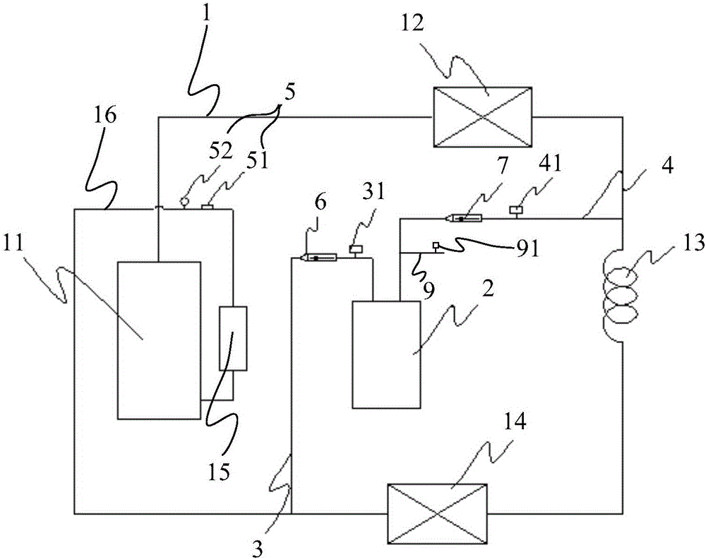
[0027]Embodiment 1: The detection system 5 includes a first temperature detection unit (not shown in the figure), a second temperature detection unit (not shown in the figure) and a third temperature detection unit 51, the first temperature detection unit is used to detect evaporation The temperature T1 of the refrigerant at the inlet of the evaporator 14, the second temperature detection unit is used to detect the temperature T2 of the refrigerant in the middle of the pipeline of the evaporator 14, the third temperature detection unit 51 is used to detect the temperature T3 of the refrigerant in the return air pipe 16 of the compressor, and the second The first temperature detection unit, the second temperature detection unit and the third temperature detection unit 51 are all connected to the control unit. Therefore, if T2-T1>0, that is, the temperature of the refrigerant in the middle of the pipeline of the evaporator 14 is greater than the temperature of the refrigerant at ...

Embodiment 2

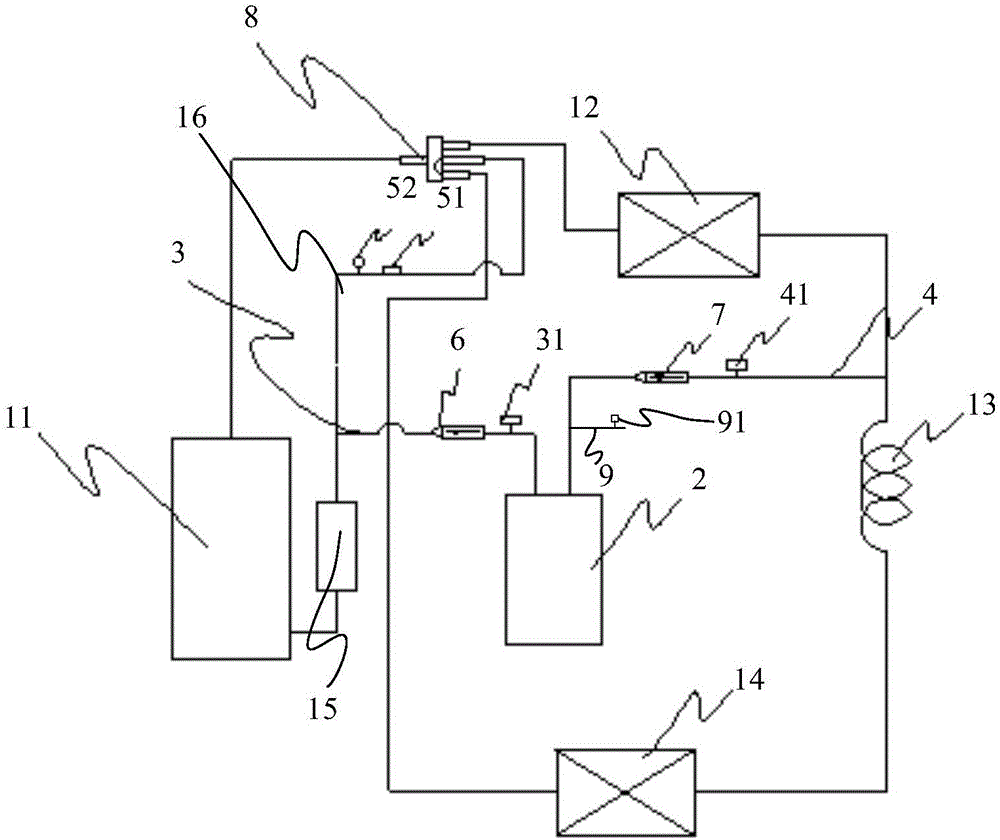
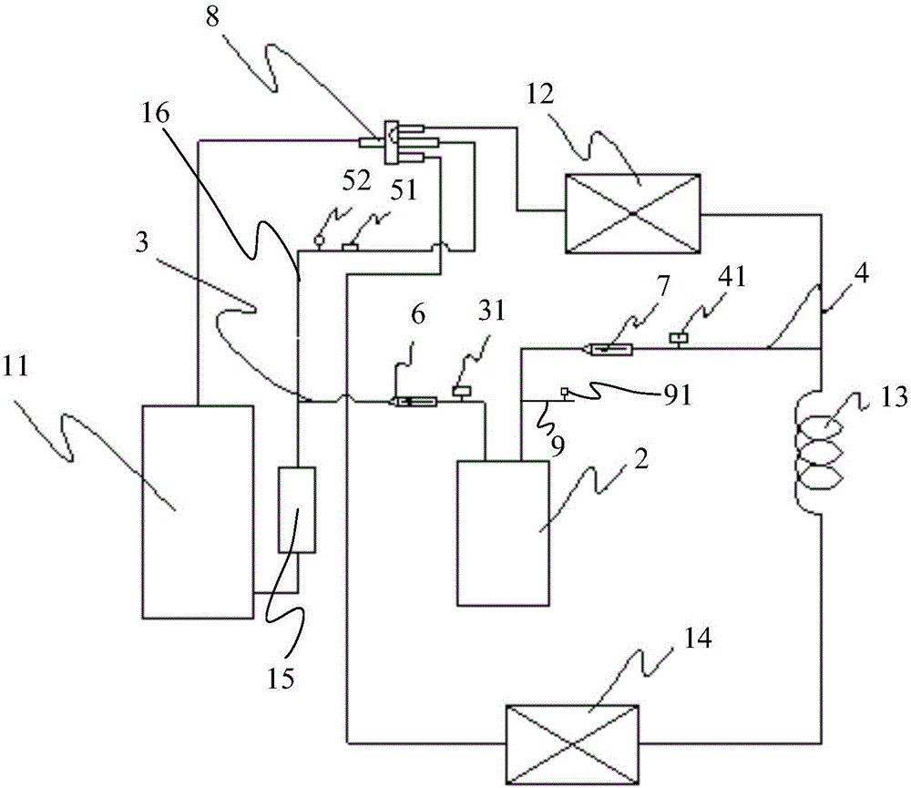
[0033] Embodiment 2: The detection system 5 includes a pressure detection unit 52 for detecting the refrigerant pressure in the air return pipe 16 of the compressor, and the pressure detection unit 52 is connected with the control unit. Therefore, if P is less than the minimum value within the preset threshold range, it means that the refrigerant in the refrigerant circulation circuit 1 is insufficient, and the control unit determines that the refrigerant in the refrigerant circulation circuit 1 is insufficient, and controls to open the charging valve 31 to circulate the refrigerant. The circuit 1 is filled with refrigerant. After opening the charging valve 31, if P is within the preset threshold range, the control unit closes the charging valve 31 to complete the charging process; if P is greater than the maximum value within the preset threshold range, It means that there is too much refrigerant in the refrigerant circulation circuit 1, and the control unit determines that th...

Embodiment 3

[0036] Embodiment 3: The detection system 5 includes a first temperature detection unit, a second temperature detection unit, a third temperature detection unit 51 and a pressure detection unit 52, the first temperature detection unit is used to detect the temperature T1 of the refrigerant at the inlet of the evaporator 14, The second temperature detection unit is used to detect the temperature T2 of the refrigerant in the middle of the pipeline of the evaporator 14, the third temperature detection unit 51 is used to detect the temperature T3 of the refrigerant in the return air pipe 16 of the compressor, and the pressure detection unit 52 is used to detect the return temperature of the compressor. The refrigerant pressure P in the gas pipe 16, and the first temperature detection unit, the second temperature detection unit, the third temperature detection unit 51 and the pressure detection unit 52 are all connected to the control unit. Therefore, if T2-T1>0, it means that the r...


PUM


Abstract

The invention discloses a refrigerant circulation system and a control method thereof and relates to the technical field of refrigeration equipment. The problems that the quantity of refrigerants in a refrigerant circulation loop cannot be adjusted automatically in the prior art, so that the refrigeration or heating process of a refrigerant circulation system cannot be in the optimal state are solved. The refrigerant circulation system provided by the invention comprises a compressor, a condenser, a throttling valve, an evaporator and a liquid storage tank which are sequentially connected to form a refrigerant circulation loop, and the refrigerant circulation system further comprises a refrigerant storage device; a refrigerant feeding pipe and a refrigerant returning pipe are connected between the refrigerant storage device and the refrigerant circulation loop; a refrigerant feeding valve is connected to the refrigerant feeding pipe in series; and a refrigerant returning valve is connected to the refrigerant returning pipe in series. The refrigerant circulation system further comprises a detection system and a control unit, the detection system is used for detecting the parameter of refrigerants in the refrigerant circulation loop, and the control unit is used for controlling the refrigerant feeding valve or the refrigerant returning valve to be opened according to the detection result of the detection system. The refrigerant circulation system can be used for automatically adjusting the quantity of the refrigerants in the refrigerant circulation loop.

Description

technical field [0001] The invention relates to the technical field of refrigeration equipment, in particular to a refrigerant circulation system and a control method thereof. Background technique [0002] In air conditioners, refrigerators, freezers and large refrigeration units and other equipment, the refrigerant circulation system is the key structure to form cooling or heat, including compressors, condensers, throttle valves, and evaporators that are connected in sequence to form a refrigerant circulation circuit. and storage tanks, etc. The amount of refrigerant used in this refrigerant circulation circuit is different according to the external ambient temperature and the cooling and heating state. For example, in the cooling process, the amount of refrigerant used by the refrigerant circulation circuit of the air conditioner when the external ambient temperature is 42°C It is greater than the amount of refrigerant used when the external environment is 25°C. For examp...

Claims


Application Information

Patent Timeline
Patent Type & Authority Applications(China)
IPC IPC(8): F25B45/00F25B49/02F25B41/06F25B41/04F25B43/00F25B41/20F25B41/31
CPCF25B43/006F25B45/00F25B49/02F25B41/31F25B41/20Y02B30/70
Inventor 陈焕锐张文锋李德鹏陈禹贵
Owner HISENSE HOME APPLIANCES GRP CO LTD
Learn More