Interlock mechanism, electric control equipment and circuit breaker equipped with the interlock mechanism

A technology of interlock mechanism and lock, applied in the direction of circuit, protection switch operation/release mechanism, electrical components, etc., can solve problems such as low production efficiency and product yield, and inability to adjust bimetallic strips

Active Publication Date: 2019-11-12
XIAMEN HONGFA ELECTRICAL SAFETY & CONTROLS CO LTD
View PDF5 Cites 0 Cited by
  • Summary
  • Abstract
  • Description
  • Claims
  • Application Information

AI Technical Summary

Problems solved by technology

[0007] The present invention aims to provide an interlocking mechanism, an electric control device and a circuit breaker equipped with the interlocking mechanism, so as to solve the problem that the existing compact interlocking mechanism, circuit breaker or electric control device such as CN100386837C cannot adjust the bimetal Technical issues that result in low production efficiency and product yield due to adjustments

Method used


Image

  • Interlock mechanism, electric control equipment and circuit breaker equipped with the interlock mechanism
  • Interlock mechanism, electric control equipment and circuit breaker equipped with the interlock mechanism
  • Interlock mechanism, electric control equipment and circuit breaker equipped with the interlock mechanism

Examples


Embodiment 1

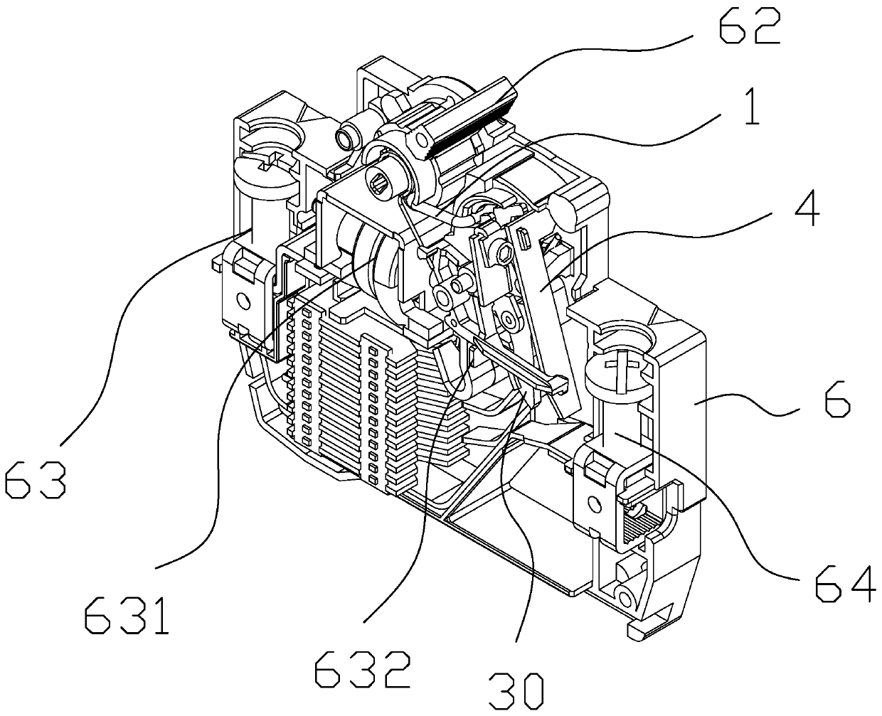
[0038] refer to figure 1 As shown, this embodiment is a circuit breaker, which, like existing circuit breakers, includes a housing 6, usually made of plastic, which is composed of two half-shell structures snapped together (for clarity expression, a half-shell structure is removed in the figure), the housing 6 is installed with a first terminal 63, a magnetic assembly 631, a static contact 632, an interlock mechanism, and a second terminal 64; the first terminal 63 , the magnetic assembly 631 and the static contact 632 are electrically connected in series in sequence, and the second terminal 64 is electrically connected to the free end of the bimetal 4 of the interlock mechanism through a conductive copper sheet and a soft connection copper wire to form a controllable Wiring group.

[0039] The housing 6 is also installed with an operating member 62. In this embodiment, the operating member 62 is a knob pivotally connected to the housing 6, and the second end of the interlock m...

Embodiment 2

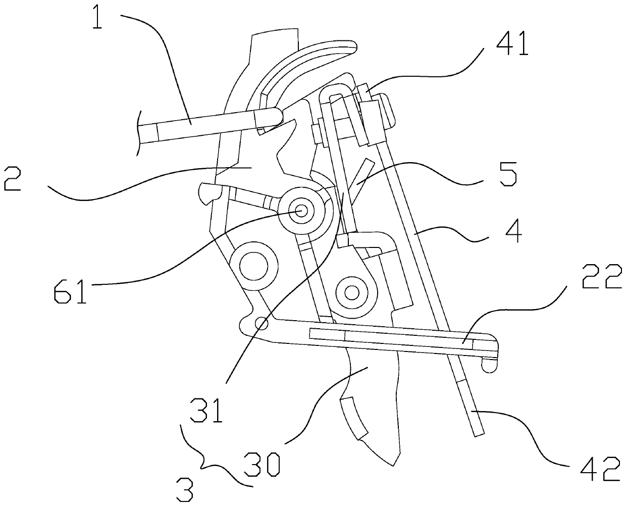
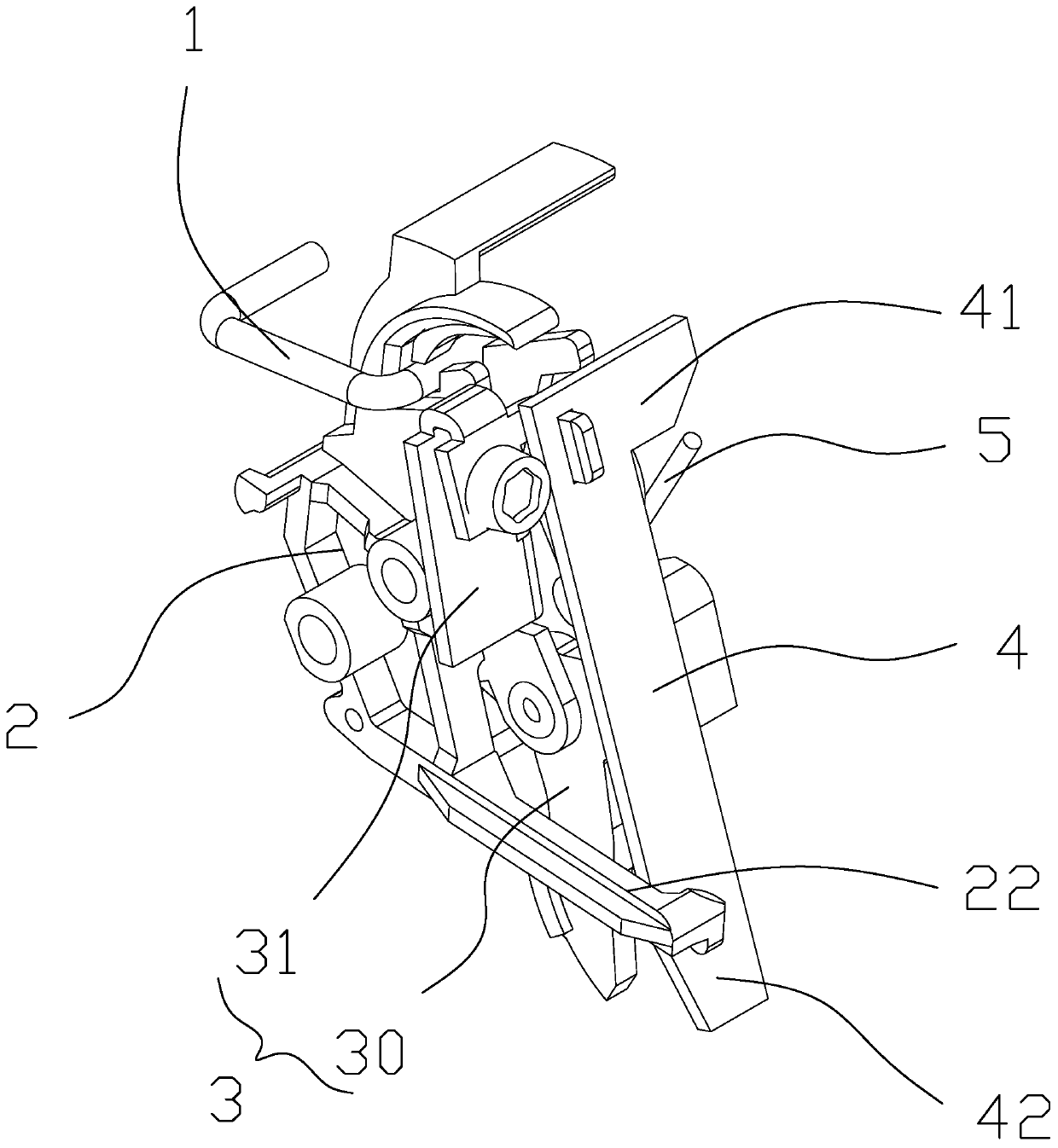
[0054] See 7 to Figure 10 , the interlock mechanism and the circuit breaker of this embodiment are basically the same as the first embodiment, the main difference is that the adjustment structure in the interlock mechanism of this embodiment is slightly different, the adjustment structure in the interlock mechanism of this embodiment is specifically : the adjustment part is a bracket 33 connected to the main body 311 of the moving contact assembly 30, and the main body 311 is basically in an "L" shape, and the fixed end 41 of the bimetal 4 is positioned on the bracket 33, The adjustment component adjusts the position of the bimetal 4 on the bracket 33 to change the relative distance between the bimetal 4 and the main body 311 of the moving contact assembly 30, thereby changing the free position of the bimetal 4. The relative position of end 42 and drive arm 22.

[0055] In this embodiment, the fixed end 41 of the bimetal 4 defines a mounting hole 410 , and the fixed end 41 o...

Embodiment 3

[0061] This embodiment is improved on the basis of Embodiment 2, and the retaining spring as the elastic member 7 of this embodiment is adjusted and designed (to become a retaining spring with an arcuate structure), so that the deformation occurs as an arcuate change, Thereby the bimetal 4 conflicts with the arc surface of the structural circlip, and the adjusting part adjusts the position of the bimetal 4 in the bracket 33 to change the arc (the nut position is adjusted to make it elastically deformed), so as to change The relative angular relationship between the bimetal 4 and the main body 311 of the moving contact assembly 30 (same as the embodiment 1, the angular swing occurs), thereby changing the relative relationship between the free end 42 of the bimetal 4 and the driving arm 22 Location.


PUM


Abstract

The invention relates to an interlocking mechanism, electric control equipment with the interlocking mechanism and a circuit breaker with the interlocking mechanism. The fixed end of a bimetallic strip of the interlocking mechanism and a moving contact assembly are connected and provided with an adjusting structure, the relative position between the free end of the bimetallic strip and a driving arm of a lock catch assembly is changed through the adjusting structure, therefore, the position of the bimetallic strip becomes adjustable, and then the technical problems that in the prior art, the production efficiency and the product yield are low due to the fact that the bimetallic strip cannot be adjusted are solved.

Description

technical field [0001] The present invention relates to the general technical field of circuit equipment, and more specifically, the present invention relates to a control wire or switch, an interlock mechanism for protecting personnel or equipment, electric control equipment and a circuit breaker equipped with the interlock mechanism. Background technique [0002] The circuit breaker for line protection includes two terminals connected to the line, and a disconnectable circuit is arranged between the two terminals; the disconnectable circuit includes a moving contact, a static contact, and a switch for controlling the position of the moving contact. The interlock mechanism also includes a thermally sensitive disconnected bimetal for protecting the circuit from overload and an electromagnetic disconnecting part containing a coil; the coil of the electromagnetic disconnecting part has a plunger-type iron core connected to the push rod, which is When the line is short-circuite...

Claims


Application Information

Patent Timeline
Patent Type & Authority Patents(China)
IPC IPC(8): H01H71/10H01H71/40H01H71/74
CPCH01H71/1009H01H71/40H01H71/7427
Inventor 李新徐明陈闽林森泉
Owner XIAMEN HONGFA ELECTRICAL SAFETY & CONTROLS CO LTD
Why Eureka
Try Eureka