Display connector and fabrication method thereof

A connector and integrated technology, which is applied in the directions of computer peripheral equipment connectors, connections, and parts of connecting devices, etc., can solve the problems of poor thermal fusion effect, skewed terminal pins, and easy deviation of the pin parts of the terminals. Improve production efficiency, ensure coplanarity, and ensure the effect of alignment

Inactive Publication Date: 2016-12-07
东莞市竞跃电子有限公司
View PDF6 Cites 3 Cited by
  • Summary
  • Abstract
  • Description
  • Claims
  • Application Information

AI Technical Summary

Problems solved by technology

However, after the upper row of terminals and the lower row of terminals are assembled, the pins are staggered with each other, the end faces of the two pins are not on the same plane, and the pins of the upper row of terminals and the lower row of terminals are staggered, and There is no plastic coating on the pin part of the terminal, and the fixing effect of the electronic pin part is not good. Yes, the coplanarity and positive position of the terminal are not easy to guarantee. Sometimes the pin part of the terminal needs to be manually adjusted, and the stability is not good; Some manufacturers have improved the above-mentioned display connectors by fixing the pins of the terminal group installed on the insulating base by hot melting, and wrapping the pins of the terminal group by plastic hot melting. However, since the end faces of the above-mentioned two pins are not on the same plane, it is easy to cause glue flow when hot-melting, and the hot-melting effect is poor, and the pins of the hot-melt front terminals are not fixed. , the lead part of the terminal is prone to deviation during the heat-melting process, and the terminal feet will be skewed after heat-melting

Method used


Image

  • Display connector and fabrication method thereof
  • Display connector and fabrication method thereof
  • Display connector and fabrication method thereof

Examples


Embodiment Construction

[0037] The present invention will be further described below in conjunction with specific embodiments and accompanying drawings.

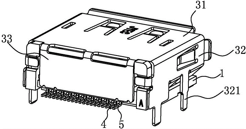
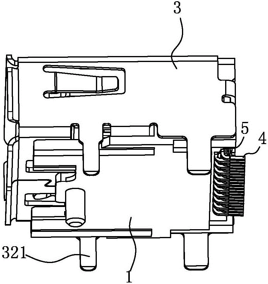
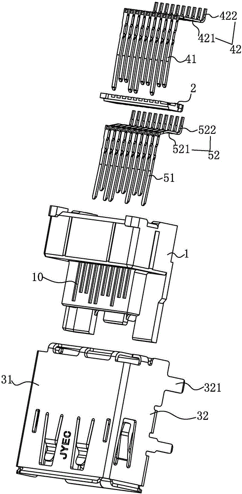
[0038] See Figure 1-3 As shown, a display connector includes: an insulating base 1, a terminal group installed on the insulating base 1, an insulating rear plug 2 installed on the rear end of the insulating base 1 to limit the terminal group and thermally coated , Metal shell 3.

[0039] See Figures 4A-4B As shown, the insulating base 1 is provided with a socket cavity 10 for terminal group installation. The socket cavity 10 is opened horizontally from the rear end to the front end of the insulating base 1. The socket cavity 10 includes the first socket cavity distributed up and down. 101 and the second socket cavity 102, the terminal group is inserted and installed in the socket cavity 10 from the rear end of the insulating base 1, a socket is formed on the front of the insulating base 1, and the external connecting plug is inserted into the s...


PUM


Abstract

The invention discloses a display connector and a fabrication method thereof. The display connector comprises an insulation base, a terminal group, an insulation rear plug and a metal shell, wherein the insulation rear plug is used for limiting and hot-melting wrapping the terminal group. In the display connector, the insulation rear plug is additionally arranged at a rear end of the insulation base, a second contact part surface of a lower-layer terminal is in contact with a bottom surface of the insulation rear plug by the insulation rear plug, a first contact part surface of an upper-layer terminal is flush with a boss surface of the insulation rear plug, the insulation rear plug is subjected to hot melting by a jig to form plastic barriers so as to wrap contact parts of the upper-layer terminal and the lower-layer terminals and achieve a fixing effect, the coplanarity and the alignment degree of welding parts of the upper-layer terminal and the lower-layer terminal can be effectively ensured, high stability is achieved, terminal pins are not needed to be adjusted by manual, and the production efficiency is improved; and moreover, after the upper-layer terminal and the lower-layer terminal are assembled, a first pin part and a second pin part are staggered vertically, and crosstalk can be enabled not to be generated in high-frequency signal transmission of the upper-layer terminal and the lower-layer terminal very well.

Description

Technical field: [0001] The invention relates to the technical field of connector products, in particular to a display connector. Background technique: [0002] The Display connector is widely used in data transmission of personal computers and servers. It is an interface specification approved by the Video Electronics Standards Association (VESA). The Display connector aims to surpass the DVI and HDMI interface technologies in several fields and provide a high-bandwidth Show interface. [0003] The display connector in the prior art basically includes: a base, an upper row of terminals installed on the base, a lower row of terminals, and a metal metal shell covering the outside of the base. The upper row of terminals of the traditional display connector After the contact portion with the lower row of terminals is inserted into the base, the pins of the upper row of terminals and the lower row of terminals protrude from the insulating base and are embedded in the slots form...

Claims


Application Information

Patent Timeline
Patent Type & Authority Applications(China)
IPC IPC(8): H01R13/502H01R13/02H01R13/516H01R13/6461H01R43/20
CPCH01R13/02H01R13/502H01R13/516H01R13/6461H01R43/20H01R2201/06
Inventor 望盛罗宇
Owner 东莞市竞跃电子有限公司
Why Eureka
Try Eureka