Plastic and iron sheet composite gasket and electromagnetic welding equipment

A technology of electromagnetic welding and composite mat, applied in chemical instruments and methods, layered products, building components, etc., can solve the problems of low melting efficiency, long melting time, poor bonding quality, etc. Good hot melt effect and fast heating effect

Pending Publication Date: 2017-09-01
WENZHOU YONG HENG TECH
View PDF3 Cites 2 Cited by
  • Summary
  • Abstract
  • Description
  • Claims
  • Application Information

AI Technical Summary

Problems solved by technology

[0002] In the construction process of construction projects, such as tunnels, subways, sewage pools, landfills, roof leaks and other projects, cement or rock mass is used as the base surface, and then plastic waterproof materials are laid on the base surface as the inner surface. However, it is very inconvenient to fix the plastic waterproof material and cement or rock mass. In the prior art, usually a plurality of plastic parts are dispersed and fixed on the cement or rock mass with nails, and then the plastic board and the plastic parts are melted on the cement or rock mass. Together, the equipment for melting includes the disclosed ultrasonic welding machine, etc. The problems of the ultrasonic welding machine are that the melting time is long, the melting efficiency is low, and the bonding quality is not good.

Method used


Image

  • Plastic and iron sheet composite gasket and electromagnetic welding equipment
  • Plastic and iron sheet composite gasket and electromagnetic welding equipment
  • Plastic and iron sheet composite gasket and electromagnetic welding equipment

Examples


Embodiment Construction

[0028] The present invention will now be further explained in conjunction with the drawings:

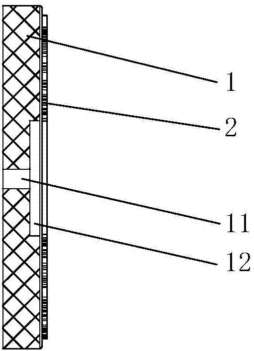
[0029] As shown in the figure, a plastic iron sheet composite gasket includes:

[0030] The plastic sheet 1 is provided with a first through hole 11;

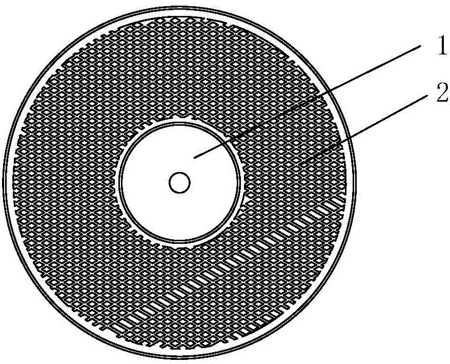
[0031] The iron sheet 2 is provided with a second through hole, the plastic sheet 1 and the iron sheet 2 are connected to form a composite gasket, and the second through hole is directly connected to the first through hole 11.

[0032] The iron sheet 2 is a mesh sheet or a porous sheet.

[0033] The plastic sheet 1 is provided with a cavity 12 that communicates with the first through hole 11.

[0034] The composite gasket is round or polygonal.

[0035] The plastic sheet 1 and the iron sheet 2 are integrally connected by injection molding, glue bonding, rivet riveting or metal nails to form a composite gasket.

[0036] The iron sheet 2 is turned into a cover shape, and the cover-shaped iron sheet 2 is covered outside the plastic sheet 1.

[0037] A...


PUM


Abstract

The invention discloses a plastic and iron sheet composite gasket and electromagnetic welding equipment. The plastic and iron sheet composite gasket comprises a plastic sheet and an iron sheet, wherein a first through hole is formed in the plastic sheet; a second through hole is formed in the iron sheet; the plastic sheet and the iron sheet are connected together to form the composite gasket; the second through hole is directly communicated with the first through hole; the iron sheet is a net-shaped or porous sheet; the plastic sheet is provided with a first concave cavity, and the concave cavity is communicated with the first through hole. The electromagnetic welding equipment comprises an electromagnetic control box and an electromagnetic gun, wherein a control driver is arranged in the electromagnetic control box; the electromagnetic gun comprises a gun cylinder, a gun handle, an electromagnetic coil, a non-magnetic conduction press ring and a switch; the gun handle is structurally connected with the gun cylinder; the electromagnetic coil is fixedly arranged at the front end of the interior of the gun cylinder, and is electrically connected with the control driver, and the electromagnetic coil is used for heating the iron sheet; the non-magnetic conduction press ring is fixedly arranged at the frontmost end of the gun cylinder and is close to the electromagnetic coil; the switch is electrically connected with the control driver, and is used for controlling the energizing or deenergizing of the electromagnetic coil. The plastic and iron sheet composite gasket and the electromagnetic welding equipment have the beneficial effects that the heating speed is high, the heat melting effect is good, the adhering is firm, and the damage to the plastic plate surface is avoided.

Description

Technical field [0001] The invention relates to a plastic-iron sheet composite gasket and electromagnetic welding equipment used in construction engineering. Background technique [0002] In the construction process of construction projects, such as the construction of tunnels, subways, sewage ponds, landfills, roof leaks, etc., cement or rock mass is used as the foundation surface, and then plastic waterproof material is laid on the foundation surface as the inner surface. However, it is inconvenient to fix the plastic waterproof material with cement or rock mass. In the prior art, usually multiple plastic parts are dispersed and fixed on the cement or rock mass with nails, and then the plastic plates and plastic parts are melted on At the same time, the melting equipment includes the disclosed ultrasonic welding machine, etc. The problems of the ultrasonic welding machine are that the melting time is long, the melting efficiency is low, and the bonding quality is not good. S...

Claims


Application Information

Patent Timeline
IPC IPC(8): B32B15/08B32B3/24B32B3/30B32B7/10B32B15/02B32B37/10B32B37/06B32B37/04
CPCB32B3/266B32B3/30B32B7/10B32B15/02B32B15/08B32B37/04B32B37/06B32B37/10B32B2419/00B32B2250/02B32B2307/302
Inventor 池希色池希聪池祖国王猛
Owner WENZHOU YONG HENG TECH
Why Eureka
Try Eureka