Dynamic operating frequency control of a buck power converter having a variable voltage output

A power converter and converter technology, which can be used in output power conversion devices, high-efficiency power electronic conversion, conversion equipment without intermediate conversion to AC, etc., and can solve problems such as reduced efficiency

Active Publication Date: 2016-12-07
ASTEC INT LTD
View PDF7 Cites 0 Cited by
  • Summary
  • Abstract
  • Description
  • Claims
  • Application Information

AI Technical Summary

Problems solved by technology

VRMs typically have a significant drop in efficiency when reducing the output voltage for a given load current

Method used


Image

  • Dynamic operating frequency control of a buck power converter having a variable voltage output
  • Dynamic operating frequency control of a buck power converter having a variable voltage output
  • Dynamic operating frequency control of a buck power converter having a variable voltage output

Examples


Embodiment Construction

[0018] The following description is merely exemplary in nature and is not intended to limit the invention, application or uses.

[0019] Some instrumentation-grade and precision power supplies need to operate over a relatively wide output voltage range (eg, 3V-12V). Other power supplies (also known as power converters) require a wide trim range of output voltage, for example, 0.8V-5V, and sometimes, when the load impedance is very low (for example, less than 1Ohm), the power converter will need to output close to zero Voltage at work in continuous mode. Power converter operation at low output voltage levels relative to the nominal output voltage causes control problems. One of the low output voltage control issues is the ability to maintain continuous mode as the operating on-time becomes smaller and smaller as the output voltage decreases. Based on a number of factors including the power converter's PWM resolution, various propagation delays, rise and fall times of the acti...


PUM


Abstract

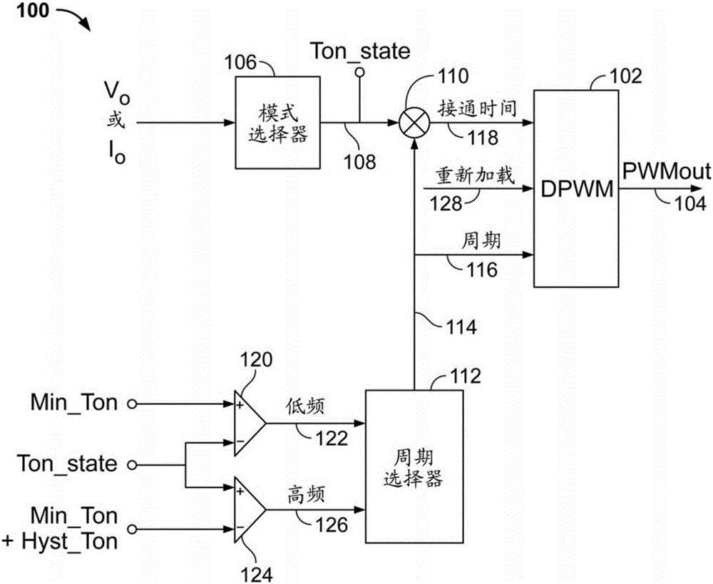
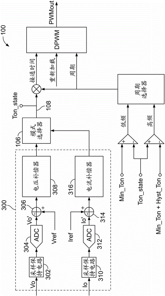
A switch controller for a variable output voltage power converter includes a pulse width modulator (PWM) output producing a pulsed signal for driving a power converter switch. A mode selector output is connected to a multiplier. A period selector output is connected to the multiplier and to a PWM input. The multiplier output is connected to another PWM input. A comparator output is connected to a period selector input. The period selector outputs a nominal cycle time to the PWM when an operating on-time state is greater than a minimum operating on-time. The period selector outputs an updated cycle time greater than the nominal cycle time when the operating on-time state is less than the minimum operating on-time causing the PWM to output a pulsed signal with the updated cycle time and a duty cycle equal to a duty cycle of an immediately preceding pulsed signal.

Description

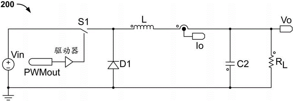
technical field [0001] The present invention relates to controlling the switching operating frequency of a buck power converter or a modified buck power converter having a variable voltage output. More specifically, the present invention relates to reducing the switching operating frequency while maintaining a duty cycle that prevents the continuous mode on-time from dropping below the continuous mode minimum on-time. Background technique [0002] The statements in this section merely provide background information related to the present disclosure and may not constitute prior art. [0003] For buck converters and any variants, such as forward converters or bridge converters, in continuous inductor current mode, the operating duty cycle (D) is defined as: [0004] D=V out ÷V in (1) [0005] Among them, V out is the output voltage of the converter, V in is the input voltage of the converter. [0006] For power converters that need to operate within a finely adjustable...

Claims


Application Information

Patent Timeline
IPC IPC(8): H02M3/156
CPCH02M1/15H02M3/156H02M3/33507Y02B70/10H02M1/0032H02M3/04
Inventor 维贾伊·G·帕德克扬西·丰塔尼拉·博卡托
Owner ASTEC INT LTD
Why Eureka
Try Eureka