

Glass tube cutting equipment
A technology for cutting equipment and glass tubes, used in glass manufacturing equipment, glass cutting devices, manufacturing tools, etc.
- Summary
- Abstract
- Description
- Claims
- Application Information
AI Technical Summary
Problems solved by technology
Method used
Image

Examples
Embodiment 1
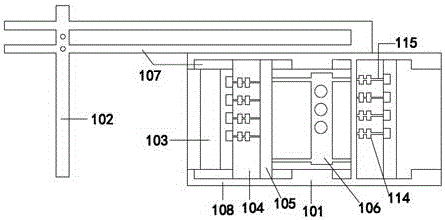
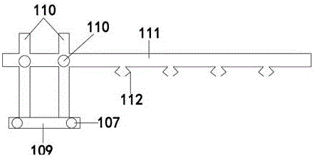
[0016] Such as figure 1 As shown, a glass tube cutting device includes a support 101 , a mechanical arm 102 , a net 103 , two rotators 104 , a cutter 105 , and a heating device 106 . Wherein said support comprises 6 support guide rails 107, support side platform 108, and described support is the cuboid of hollow out, has 2 in described support guide rail 107 and is positioned at the upper surface of support side platform 108, and 2 are welded on described support side platform 108 outer sides, 2 embedded in the support and parallel to the support side platform 108; the bottom end of the mechanical arm 102 is penetrated by the support table side guide rail and suspended above the support; the mechanical arm 102 includes a platform 109, two support bars 110, a support arm 111, three machine fingers 112, and two knobs 113; the platform 109 is arranged at the lowermost end of the mechanical arm 102, and the platform 109 is covered by the support The side guide rail runs through; ...
Embodiment 2
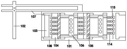
[0019] Such as Figure IIAs shown, a glass tube cutting device includes a support 101 , a mechanical arm 102 , a connecting net 103 , three rotators 104 , two cutters 105 , and two heating devices 106 . Wherein said support comprises 6 support guide rails 107, support side platform 108, and described support is the cuboid of hollow out, has 2 in described support guide rail 107 and is positioned at the upper surface of support side platform 108, and 2 are welded on described support side platform 108 outer sides, 2 embedded in the support and parallel to the support side platform 108; the bottom end of the mechanical arm 102 is penetrated by the support table side guide rail and suspended above the support; the mechanical arm 102 includes a platform 109, 2 support rods 110, a support arm 111, 4 machine fingers 112, and 2 knobs 113; The side guide rail runs through; the support rod 110 is inserted on the platform 109 and is perpendicular to the platform 109; Parallel in the h...
PUM
 Abstract
Description
Claims
Application Information