A base station equipment room structure

A technology for base station equipment and walls, which is applied in the field of base station equipment room structure, can solve the problems of unattended, heavy maintenance and maintenance pressure, and clogging of filters, so as to reduce maintenance work intensity, reduce work time, and prolong practical life. Effect

Inactive Publication Date: 2018-05-04
郭志清
View PDF5 Cites 0 Cited by
  • Summary
  • Abstract
  • Description
  • Claims
  • Application Information

AI Technical Summary

Problems solved by technology

[0002] At present, the temperature control of the computer room of the communication base station mainly depends on the adjustment of air-conditioning equipment. Since the air-conditioning equipment needs to be turned on for a long time, it will cause problems such as high failure rate and heavy inspection and maintenance pressure. When the air-conditioning equipment is damaged, if other ventilation methods are not adopted in time, It may cause damage to the equipment in the computer room due to poor heat dissipation and ventilation, thus affecting the normal communication work
Although some ventilation devices are provided in practical applications, such as box-type multi-layer filter ventilation design and exhaust fans, etc., because most of the communication base stations are built in remote areas far away from towns and cities, and no one is guarding them, the ventilation and filtration devices cannot be used for a long time. If it is cleaned up, the filter screen will be clogged, which will seriously affect the ventilation effect.
In addition, relevant technical literature also provides some ventilation devices that can automatically remove dust, but there are still technical problems such as complex structure, high cost, and unsatisfactory dust removal effect.

Method used


Image

  • A base station equipment room structure

Examples


Embodiment 1

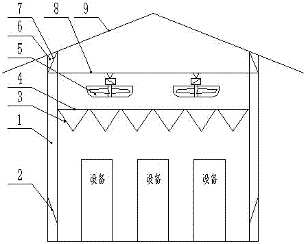
[0017] Such as figure 1 As shown, a base station equipment room structure includes four walls 1, the lower part of the wall 1 is provided with a plurality of filter screens 2, and the upper part of the room is provided with a plurality of guide plates 3, and the guide plates 3 are made of two pieces. The multiple guide plates 3 are arranged on the upper part of the equipment room through the beams 4 erected on the wall 1; one or more fixed beams 8 are also arranged above the beams 4, and each of the One or more ventilation fans 5 are arranged on the fixed beam 8;

[0018] A plurality of ventilation holes 6 are evenly distributed on the wall body 1 located between the fixed beam 8 and the roof 9 , and a top filter 7 is installed in the ventilation holes 6 .

[0019] The filter screen 2 is arranged obliquely, and the external screen surface is inclined downward.

[0020] The included angle of the guide plate 3 is not greater than 90°.

[0021] The top filter net 7 is arranged...


PUM


Abstract

The invention specifically relates to an equipment room structure of a base station. The equipment room structure is simple and has good ventilation and dust removal effects. According to the technical scheme, the equipment room structure comprises a four-surface wall body, wherein a plurality of filter screens are arranged at the lower part of the wall body, a plurality of guide plates are arranged at the upper part in an equipment room, and each guide plate is formed by two plates forming an included angle; the guide plates are arranged at the upper part of the equipment room through a crossbeam bridged on the wall body; one or more fixed beams are further arranged above the crossbeam, and one or more venting fans are arranged on each fixed beam; and a plurality of vent holes are uniformly formed in the wall body from the fixed beams to the roof, and top filter nets are mounted in the vent holes.

Description

technical field [0001] The invention specifically relates to a base station equipment room structure. Background technique [0002] At present, the temperature control of the computer room of the communication base station mainly depends on the adjustment of air-conditioning equipment. Since the air-conditioning equipment needs to be turned on for a long time, it will cause problems such as high failure rate and heavy inspection and maintenance pressure. When the air-conditioning equipment is damaged, if other ventilation methods are not adopted in time, It may cause damage to the equipment in the computer room due to poor heat dissipation and ventilation, thus affecting the normal communication work. Although some ventilation devices are provided in practical applications, such as box-type multi-layer filter ventilation design and exhaust fans, etc., because most of the communication base stations are built in remote areas far away from towns and cities, and no one is guard...

Claims


Application Information

Patent Timeline
Patent Type & Authority Patents(China)
IPC IPC(8): E04H5/02F24F7/007F24F13/28
CPCE04H5/02E04H2005/005F24F7/007F24F13/28
Inventor 郭志清
Owner 郭志清
Why Eureka
Try Eureka