Fluid pipe network leakage monitoring system

A technology for monitoring systems and fluid pipes, applied in pipeline systems, gas/liquid distribution and storage, mechanical equipment, etc., can solve problems such as incomprehensible analysis, complex structure of municipal pipe network, discounted detection data, etc., and achieve simple and effective management Effect

Inactive Publication Date: 2016-12-14
XUZHOU NORMAL UNIVERSITY
View PDF8 Cites 14 Cited by
  • Summary
  • Abstract
  • Description
  • Claims
  • Application Information

AI Technical Summary

Problems solved by technology

In addition, the structure of the municipal pipe network is complex, and it is impossible to grasp and analyze the pipe network as a whole, and in the pipe network transportation, during the propagation of the pressure wave, the pressure signal is attenuated due to factors such as working condition disturbance and system noise. Intense, the role of the final detection data will be greatly reduced

Method used


Image

  • Fluid pipe network leakage monitoring system
  • Fluid pipe network leakage monitoring system
  • Fluid pipe network leakage monitoring system

Examples


Embodiment 1

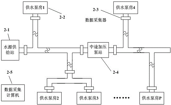
[0039] Embodiment 1: as figure 2 As shown, a distribution structure diagram of a data collector of a primary water supply system, including a water source supply station 2-1, a water supply pump room 2-2, a data collector 2-3, a midway pressurized pump station 2-4, and a data collection computer 2-5.

[0040] In the example of the present invention, the water source supply station 2-1 is responsible for delivering water source for this section of pipe network, and is the source of this section of pipe network. Each section of the pipe network is equipped with a water supply station to ensure the water supply of the section of the pipe network.

[0041] In the example of the present invention, the water supply pump room 2-2 is responsible for pressurizing the secondary water supply unit. After the water source enters the secondary water supply unit, in order to ensure that the water pressure is controlled within a certain range, the secondary pressurized water supply is carr...

Embodiment 2

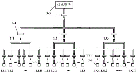
[0045] Embodiment 2: as image 3 As shown, a distribution structure diagram of data collectors in a secondary water supply system, including data collectors 3-1, users 3-2, and water supply pump rooms 3-3.

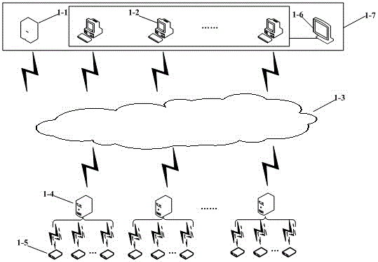
[0046] In the example of the present invention, the data collector 3-1 is used to collect the on-site data of the entrance and exit of the designated location of the pipeline, process the collected signals, convert them into standardized data, and send them to the data collection computer. This is the same as figure 1 1-4 in figure 2 2-3 in is the same type of device.

[0047] In the example of the present invention, the user 3-2 represents the terminal of the pipe network water supply system.

[0048] In the example of the present invention, the water supply pump house 3-3 is used to be responsible for pressurizing the secondary water supply unit. After the water source enters the secondary water supply unit, in order to ensure that the water pressure is controlled w...


PUM


Abstract

The invention discloses a fluid pipe network leakage monitoring system. A monitoring station receives and displays data uploaded to a server by a data collecting computer in real time; the Internet is a platform channel to transmit the data among the server, the monitoring station and the data collecting computer; the data collecting computer collects the collected data and transmits the collected data to the server or the monitoring station in real time; and a data collector is used for collecting data of pressures, quantities of flow and temperatures of the inlet and the outlet of an assigned place of a pipe, treating the collected data, transforming the collected data into data with unified standard, and transmitting the data to the data collecting computer. According to the fluid pipe network leakage monitoring system, a whole pipe network is adopted to monitor states of the pipe in real time; the collected data can be transmitted for operation in a wired mode or in a wireless mode according to actual demands of sites; specific status of the pipe can be monitored conveniently in time; features, quantities and positions of pipe leakages are judged; and the whole pipe network can be analyzed and managed; and an expert system is formed.

Description

technical field [0001] The invention relates to the technical field of internal detection methods of pipeline networks, in particular to a system for monitoring fluid pipeline network leakage. Background technique [0002] As the most commonly used mode of transportation, pipeline transportation has the characteristics of high efficiency, low cost, safety and stability, and it is also easy to manage, so pipeline transportation plays a pivotal role in fluid transportation. In municipal planning, pipeline transportation also faces some problems, the most prominent one being pipeline leakage. Since pipelines are mostly transported underground, pipelines are prone to leakage due to corrosion, perforation or man-made damage over time due to factors such as underground media, geographical environment, and materials. This will lead to waste of resources, economic losses, and even casualties, which completely runs counter to the sustainable development advocated today. Therefore, ...

Claims


Application Information

Patent Timeline
Patent Type & Authority Applications(China)
IPC IPC(8): F17D5/02
CPCF17D5/02
Inventor 张兴奎王俊张彩荣吴天琦
Owner XUZHOU NORMAL UNIVERSITY
Why Eureka
Try Eureka