An array zero-setting laser large working distance auto-collimation device and method

A technology of working distance and self-collimation, which is applied in the field of precision measurement and optical engineering, and can solve the problems that self-collimation and micro-angle measurement cannot be realized, the range should not be too large, and the reflected beam deviates from the entrance pupil, etc.

Active Publication Date: 2016-12-14
HARBIN INST OF TECH
View PDF3 Cites 6 Cited by
  • Summary
  • Abstract
  • Description
  • Claims
  • Application Information

AI Technical Summary

Problems solved by technology

[0008] First, the range of the angle between the normal of the mirror surface of the measured object 5 and the optical axis of the laser autocollimator should not be too large, otherwise the reflected beam will deviate from the entrance pupil of the laser autocollimator optical system, resulting in failure to achieve self-collimation Straight and micro angle measurement;
[0009] Second, the distance between the mirror surface of the measured object 5 and the entrance pupil of the la

Method used


Image

  • An array zero-setting laser large working distance auto-collimation device and method
  • An array zero-setting laser large working distance auto-collimation device and method
  • An array zero-setting laser large working distance auto-collimation device and method

Examples


specific Embodiment 1

[0083] This embodiment is an embodiment of an array zeroing laser large working distance autocollimation device.

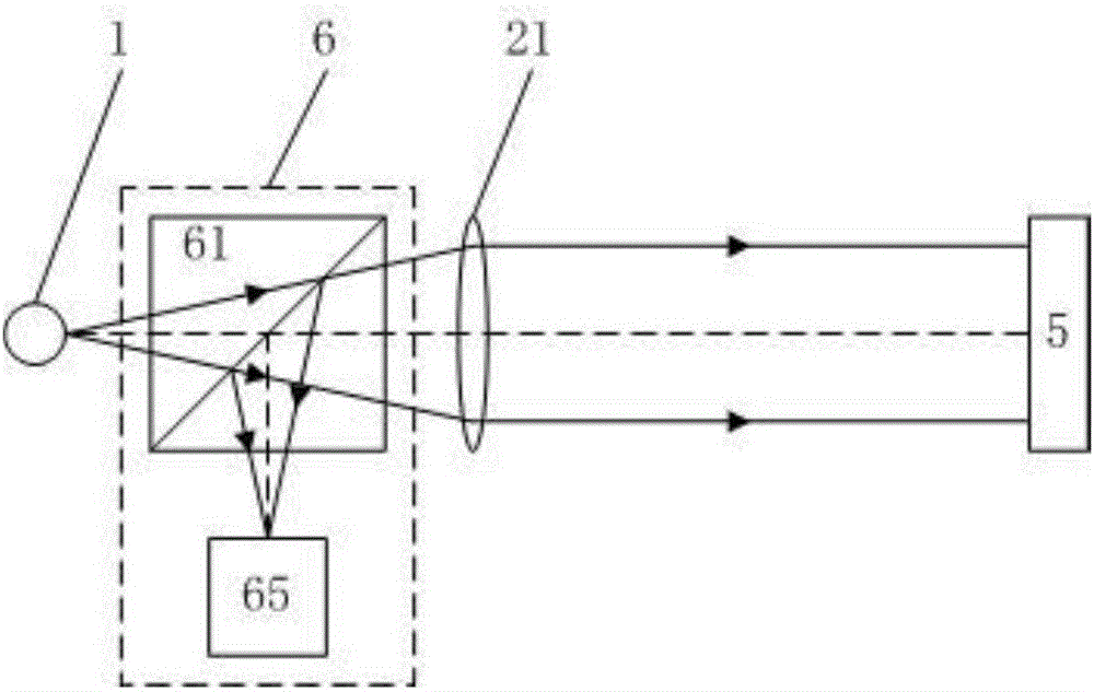
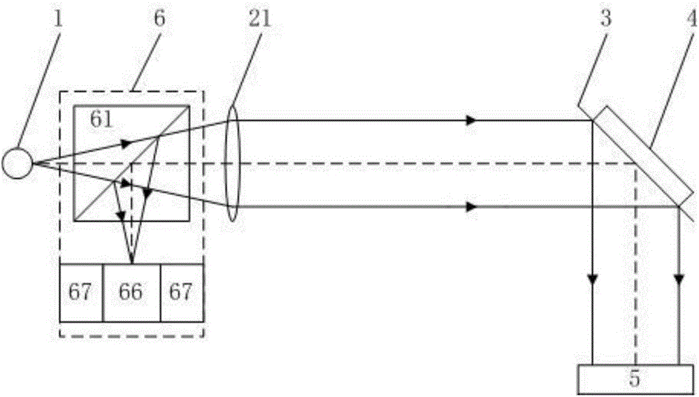
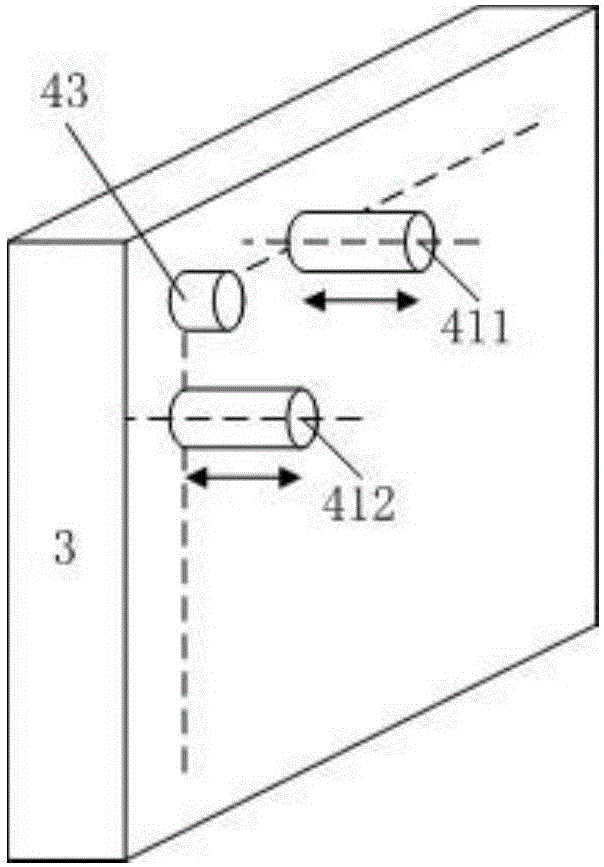
[0084] The structure diagram of the array zeroing laser large working distance self-collimation device in this embodiment is as follows figure 2 shown. The self-collimation device includes a light source 1, a transmissive collimator mirror 21, a reflector 3, and a feedback imaging system 6. The reflector 3 is provided with an angle adjustment measuring device 4; After the straight mirror 21 is collimated into a parallel light beam, it is reflected by the reflector 3 and incident on the surface of the measured object 5; the light beam reflected from the surface of the measured object 5 is then reflected by the reflective mirror 3 and collected by the feedback imaging system 6 imaging;

[0085] The feedback imaging system 6 is arranged between the light source 1 and the transmissive collimator 21, including a first feedback beam splitter 61, a four-quadrant detec...

specific Embodiment 2

[0088] This embodiment is an embodiment of an array zeroing laser large working distance autocollimation device.

[0089] The structure diagram of the array zeroing laser large working distance self-collimation device in this embodiment is as follows Figure 7 shown. On the basis of the specific embodiment 1, the array zeroing laser large working distance self-collimation device of this embodiment is also provided with a wavefront detection system 7 and a wavefront compensation system 8;

[0090] The wavefront detection system 7 includes a wavefront detection spectroscope 71 and an air disturbance wavefront detector 72; the wavefront detection spectroscope 71 is arranged between the reflector 3 and the measured object 5, and the air disturbance wavefront detector 72 is arranged on the reflected optical path of the wavefront detection spectroscope 71, and the mirror deformation wavefront detector 73 is arranged on the secondary reflected optical path of the reflector 3;

[00...

specific Embodiment 3

[0092] This embodiment is an embodiment of an array zeroing laser large working distance autocollimation device.

[0093] The structure diagram of the array zeroing laser large working distance self-collimation device in this embodiment is as follows Figure 8 shown. On the basis of the specific embodiment 1, the array zeroing laser large working distance self-collimation device of this embodiment is also provided with a wavefront detection system 7 and a wavefront compensation system 8;

[0094] The wavefront detection system 7 includes a wavefront detection beamsplitter 71 and a mirror deformation wavefront detector 73; the wavefront detection beamsplitter 71 is arranged between the mirror 3 and the measured object 5, and the air disturbance wavefront detection The device 72 is arranged on the reflected optical path of the wavefront detection spectroscope 71, and the mirror deformation wavefront detector 73 is arranged on the secondary reflected optical path of the reflecto...


PUM


Abstract

The invention belongs to the field of precision measurement technology and optical engineering, and specifically relates to an array zero-setting laser large working distance auto-collimation device and method. The device is composed of a light source, a collimating mirror, a reflector and a feedback imaging system. In the method, by adjusting the reflector, a reflected beam is returned to the center of an image plane of the feedback imaging system, and then an angular deflection measuring device on the reflector is used to obtain angle changes of the surface of a measured object. In the invention, since the reflector is added to the conventional auto-collimating angle measuring system, it is possible to avoid the problem that measuring can not be carried out since reflected light of the measured object deviates from the measuring system, so that the advantage of increasing the auto-collimation range at the same working distance or increasing the working distance in same auto-collimation range are realized. In addition, the specific design of the collimating mirror, the feedback imaging system, the reflector and the like make the device of the invention simple in structure, low in production cost, and capable of performing measurement in an unstable measurement environment; and a technical advantage of rapid measurement is realized.

Description

technical field [0001] The invention belongs to the field of precision measurement technology and the field of optical engineering, in particular to an array zeroing laser large working distance self-collimation device and method. Background technique [0002] In the fields of precision measurement technology, optical engineering, cutting-edge scientific experiments and high-end precision equipment manufacturing, there is an urgent need for large working range and high-precision laser self-collimation technology at a large working distance. It supports the development of technology and equipment in the above fields. [0003] In the field of precision measurement technology and instruments, the combination of laser autocollimator and circular grating can measure any line angle; the combination of laser autocollimation technology and polyhedral prism can measure surface angle and circular indexing; the maximum working distance From a few meters to hundreds of meters; resoluti...

Claims


Application Information

Patent Timeline
IPC IPC(8): G01B11/26G01C15/00
CPCG01B11/26G01C15/002
Inventor 谭欣然邢耀龙赵宇航王超谭久彬
Owner HARBIN INST OF TECH
Why Eureka
Try Eureka